In part 2 of the tutorial we will work on the exterior details. You can check out the previous tutorials
here.
In part 1 we learned how to use many of the common tools, while illustrating the
benefits of components & layers.
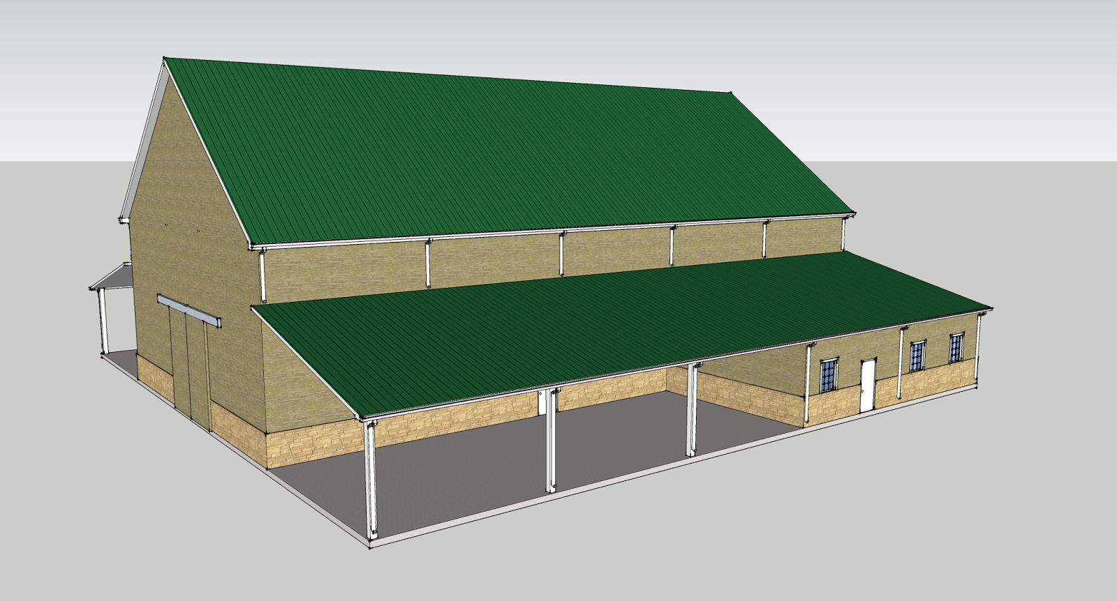 |
| The barn with added exterior details. |
Start by adding the bay doors. The bay door will be 13'x14'. Hit the
rectangle tool or key in
r. Click to start the rectangle and key in
6.5',14' and hit enter.
 |
| Use the rectangle tool to draw your door. |
Hit the
push/pull tool or key in
p. Click the face of your rectangle, move the mouse up, and key in
4" for the door thickness.
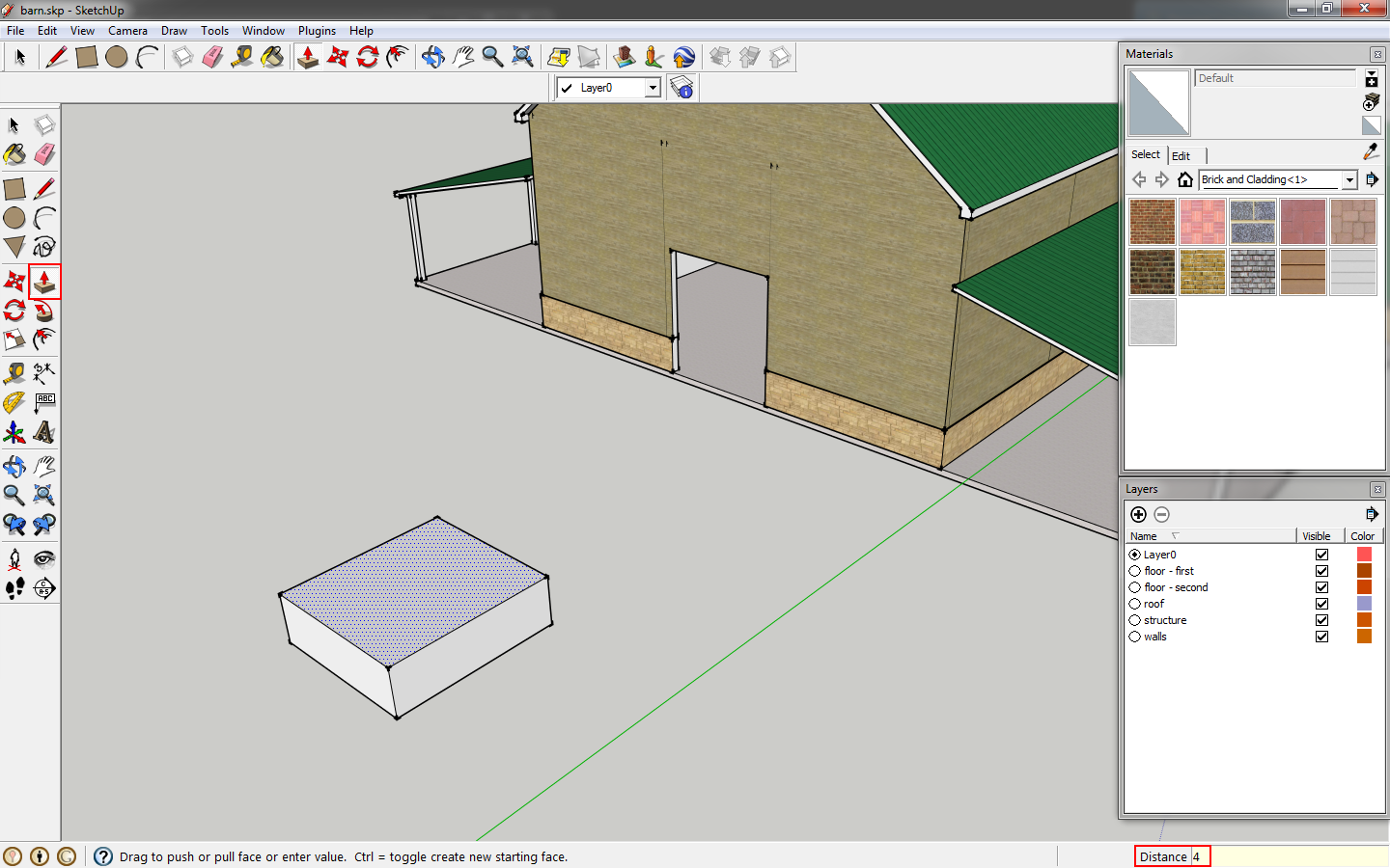 |
| Use push/pull to extrude the door |
Select the box, and use the
rotate tool or key in
q. Click the corner of your door and drag the rotate icon until it is red, indicating it is aligned with an axis. Key in
90 to rotate it 90 degrees.
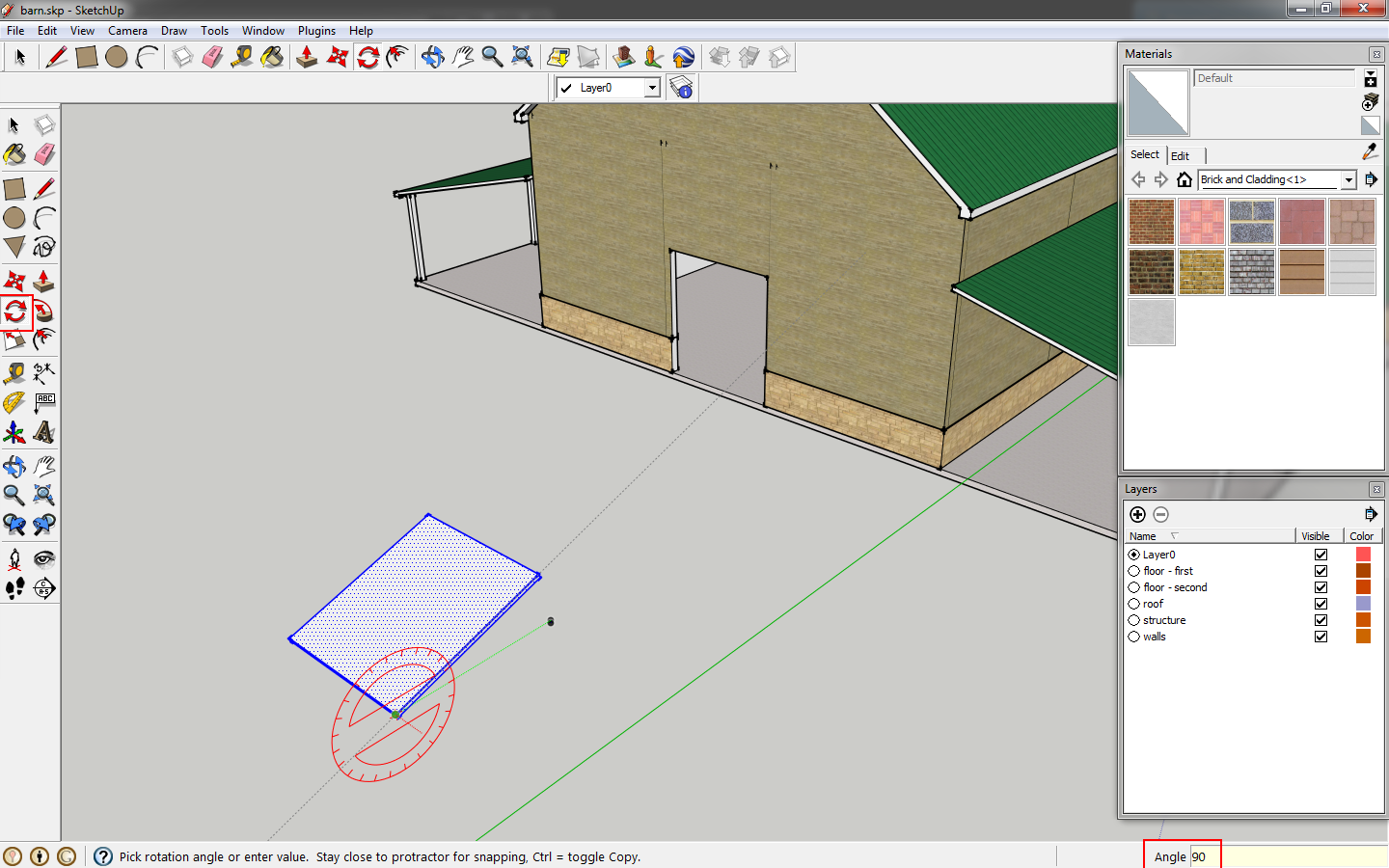 |
| Rotate the door. |
While the door is still selected, right click, and select
Make Component, proving an unique name.
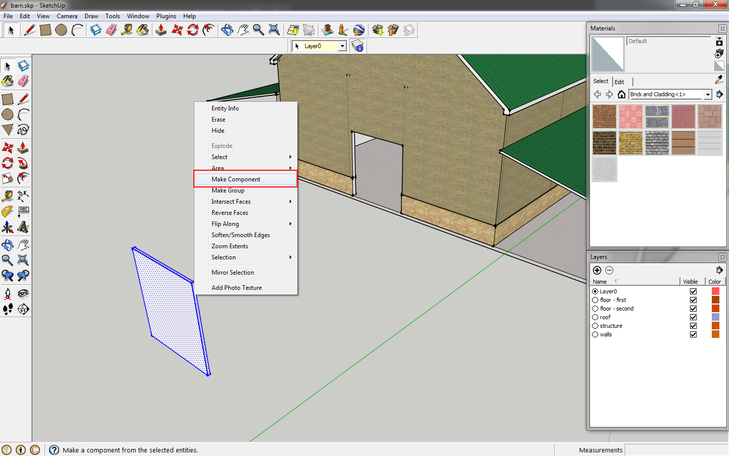 |
| Make the door a component. |
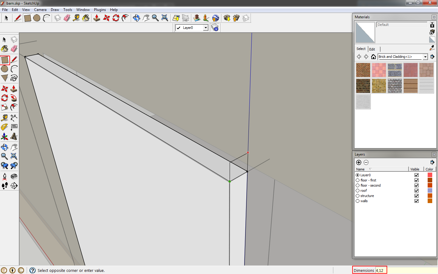
Double click to edit the component. For the rail, start drawing a rectangle, keying in
4,12.
 |
| Draw a rectangle for the door rail. |
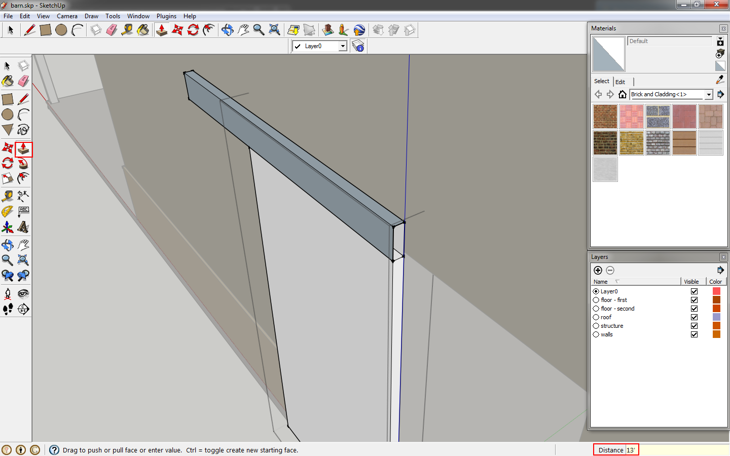
Use
push/pull to extrude it 13'. This is twice the length of the door.
 |
| Extrude the rail. |
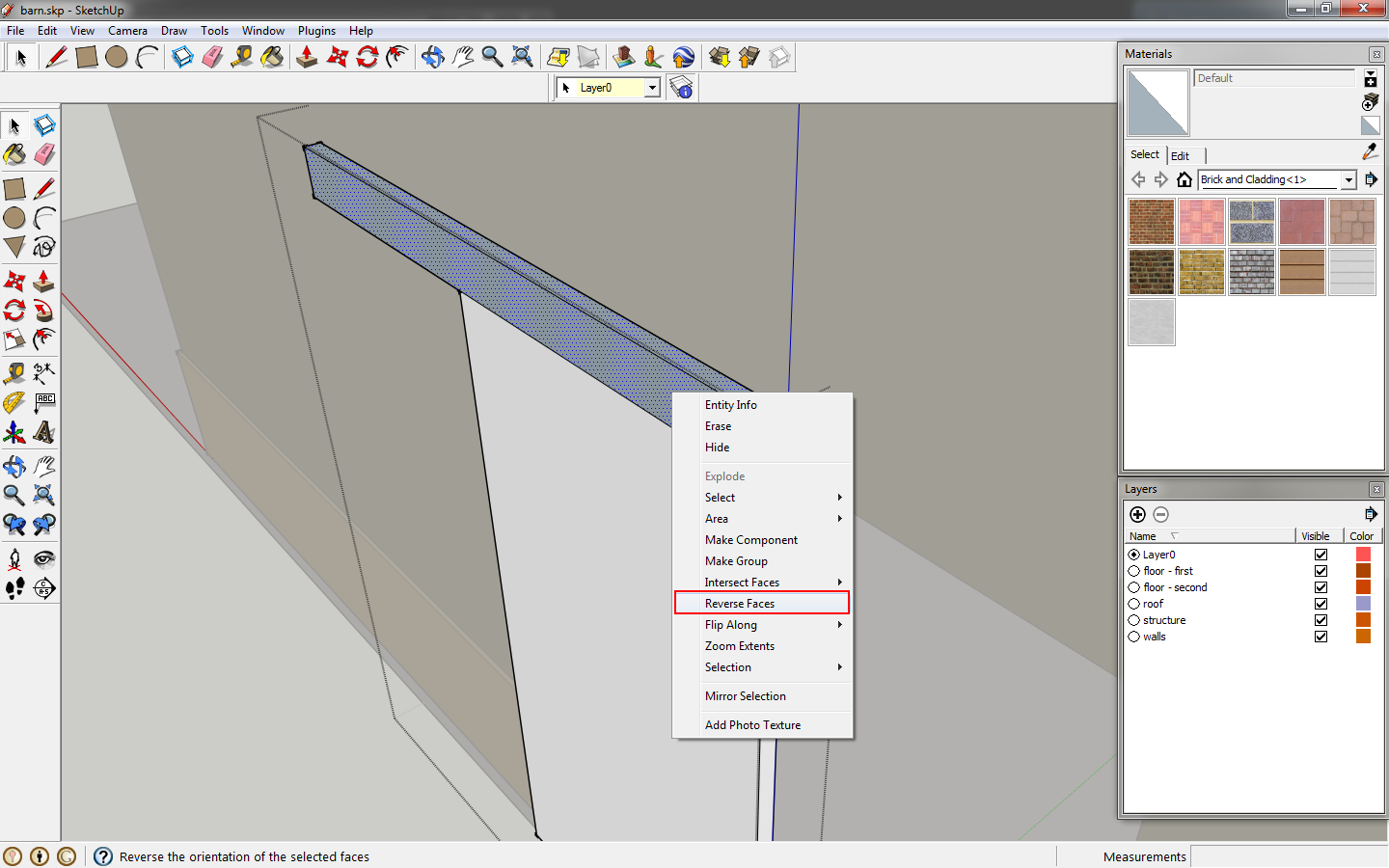
If your faces are reversed on the rail, where the faces are purple and not white, select the faces, right click and select
reverse faces. While this may not matter if you add materials, it will make a difference in some rendering programs. A good practice is to always have the faces right side out.
 |
| Reverse the faces if they are backwards. |
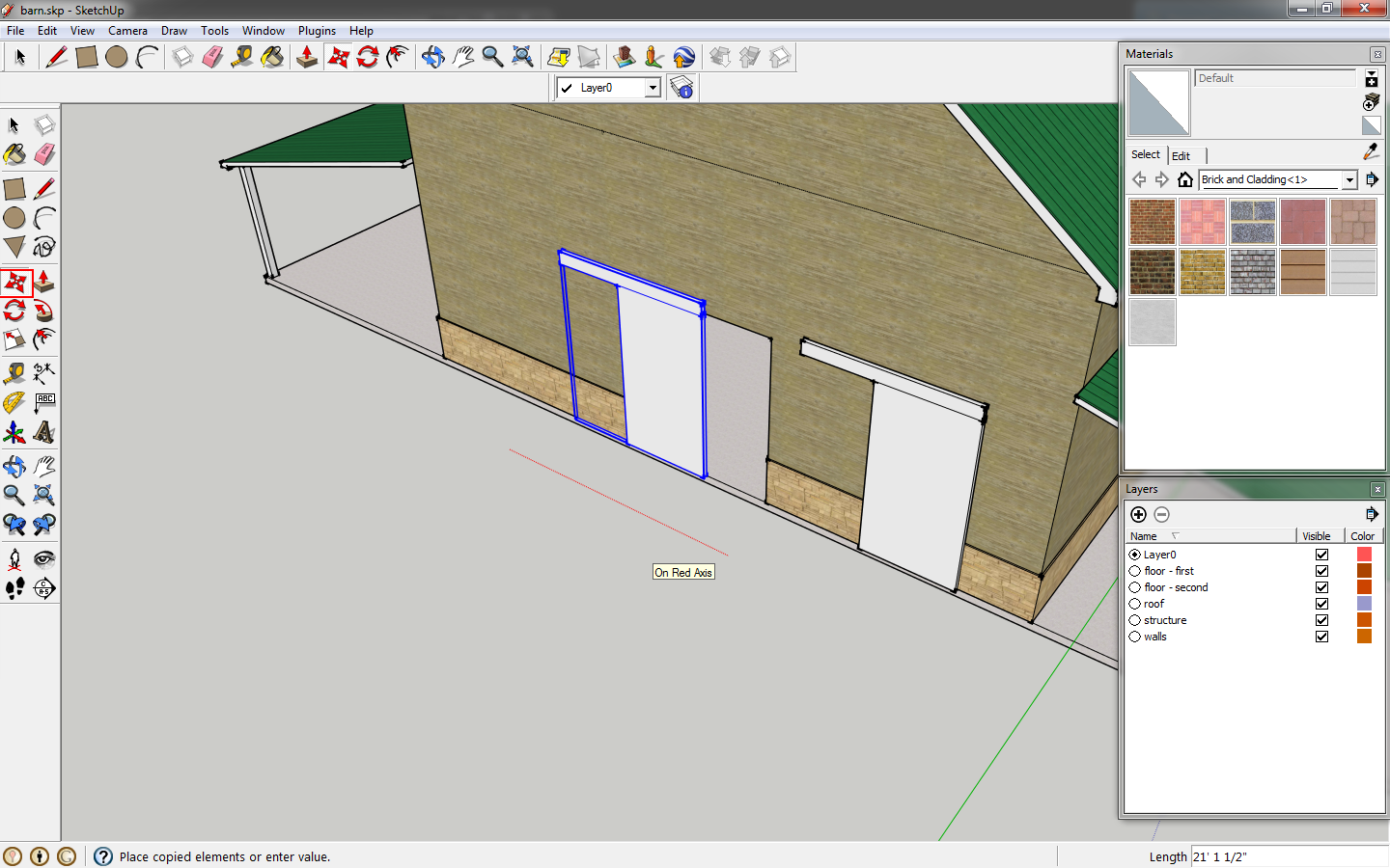
Finish editing the component. Click the door and use the
move tool to move the corner of the door to the corner of the opening. Then move the door again, clicking
ctrl to duplicate the door.
 |
| Move the door to the opening and then copy it. |
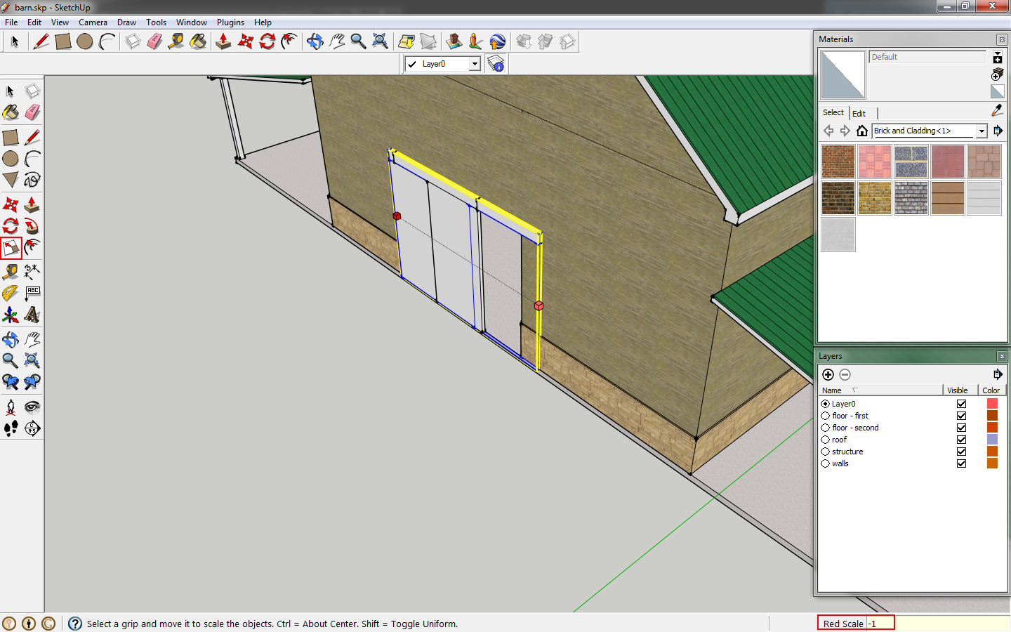
Click the
scale tool or
s, click on of the side grip points and key in
-1. This will mirror the door.
 |
| Mirror the duplicate. |
Move the mirrored door so that the corners of your two doors match.
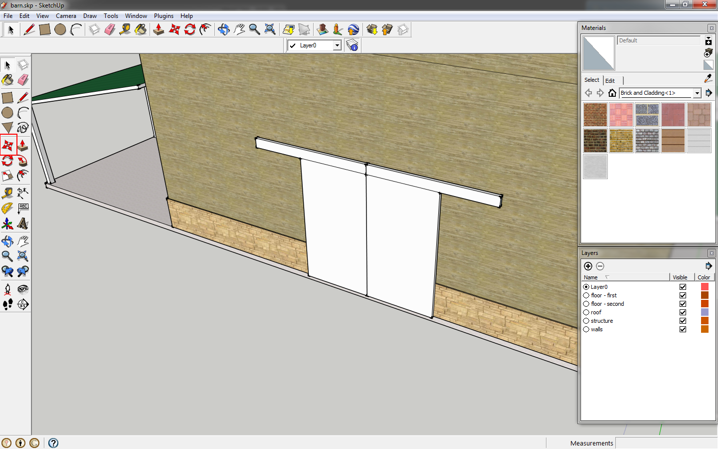 |
| Move the door in place. |
Double click one of the doors to begin editing. Editing one door will edit both since it's a component. Select the
eraser tool or key in
e. While holding shift click the lines where the rail meets. This will hide the lines.
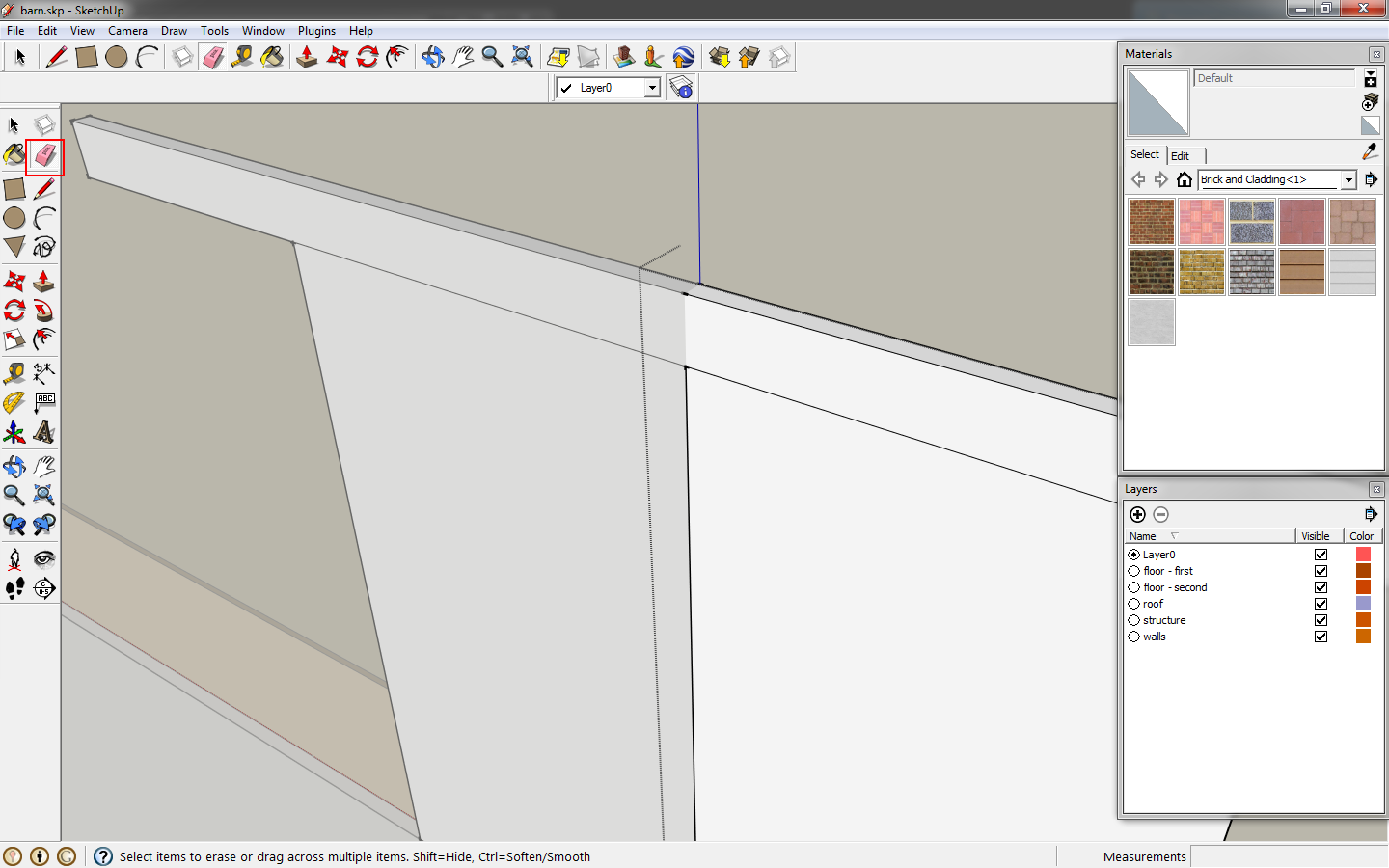 |
| Hide the lines where the rails meet. |
Click
b to bring up the
materials window, or go to the menu, click
window>materials. In the drop down box in the
materials window select
Metal. Choose a material by left clicking and the cursor will change to a paint bucket. Click on the faces of the rail to apply the material.
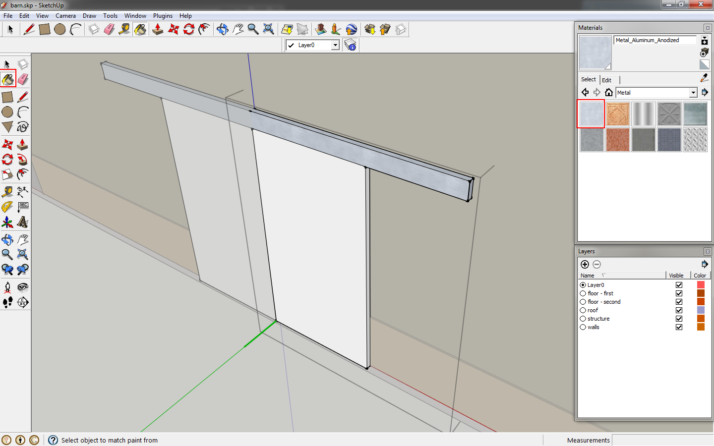 |
| Add a material to the rail. |
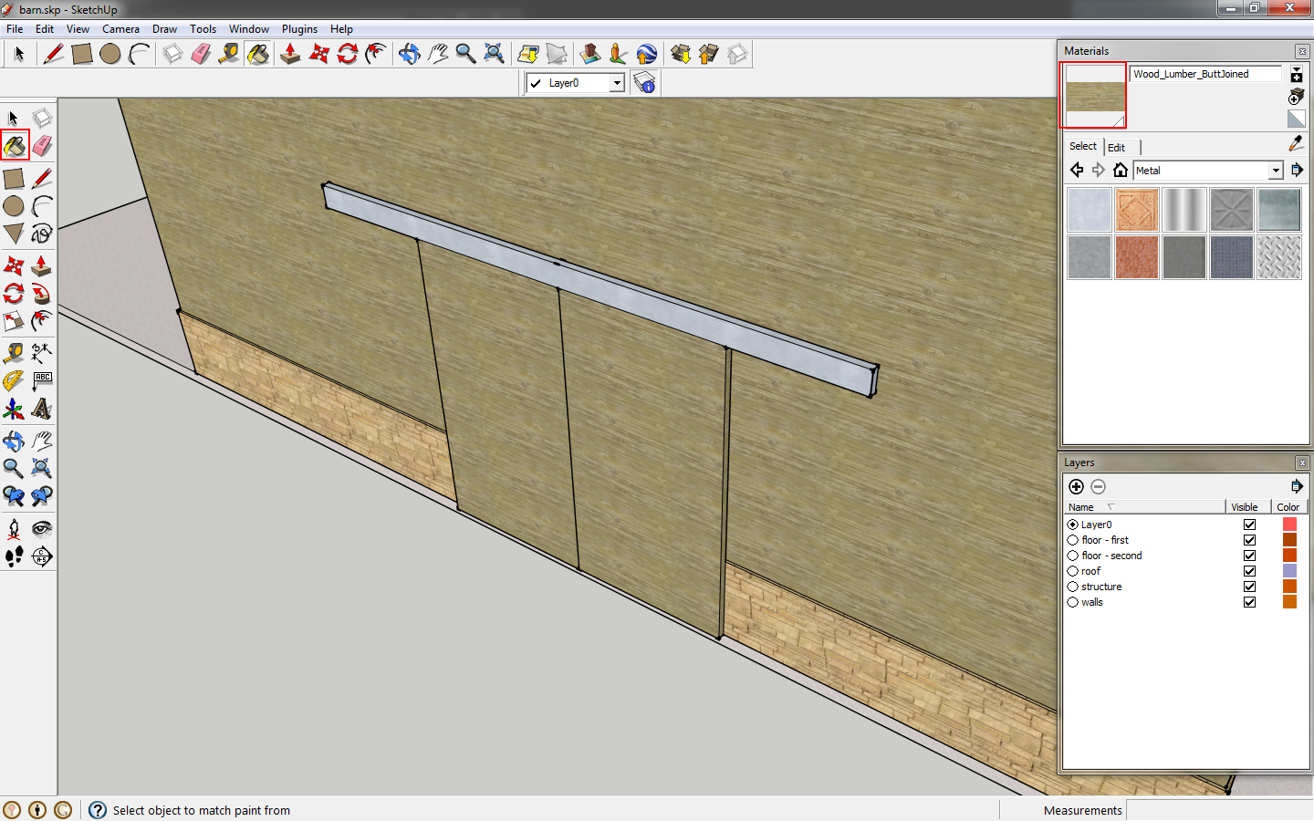
Finish editing the component by double clicking outside of the component editing box. If your cursor is no longer the paint bucket, click
b to activate it. Hold
alt and click the wall of the barn. Then left click the door component to apply the wall material. The rail remains metal because we edited the component. This allows you to change door materials while maintaining the rail material.
 |
| Apply a material to the door components. |
Now we will add a gutter. Start with a 4"x4" rectangle, adding a sloping front and lip. Select the profile and make it a component.
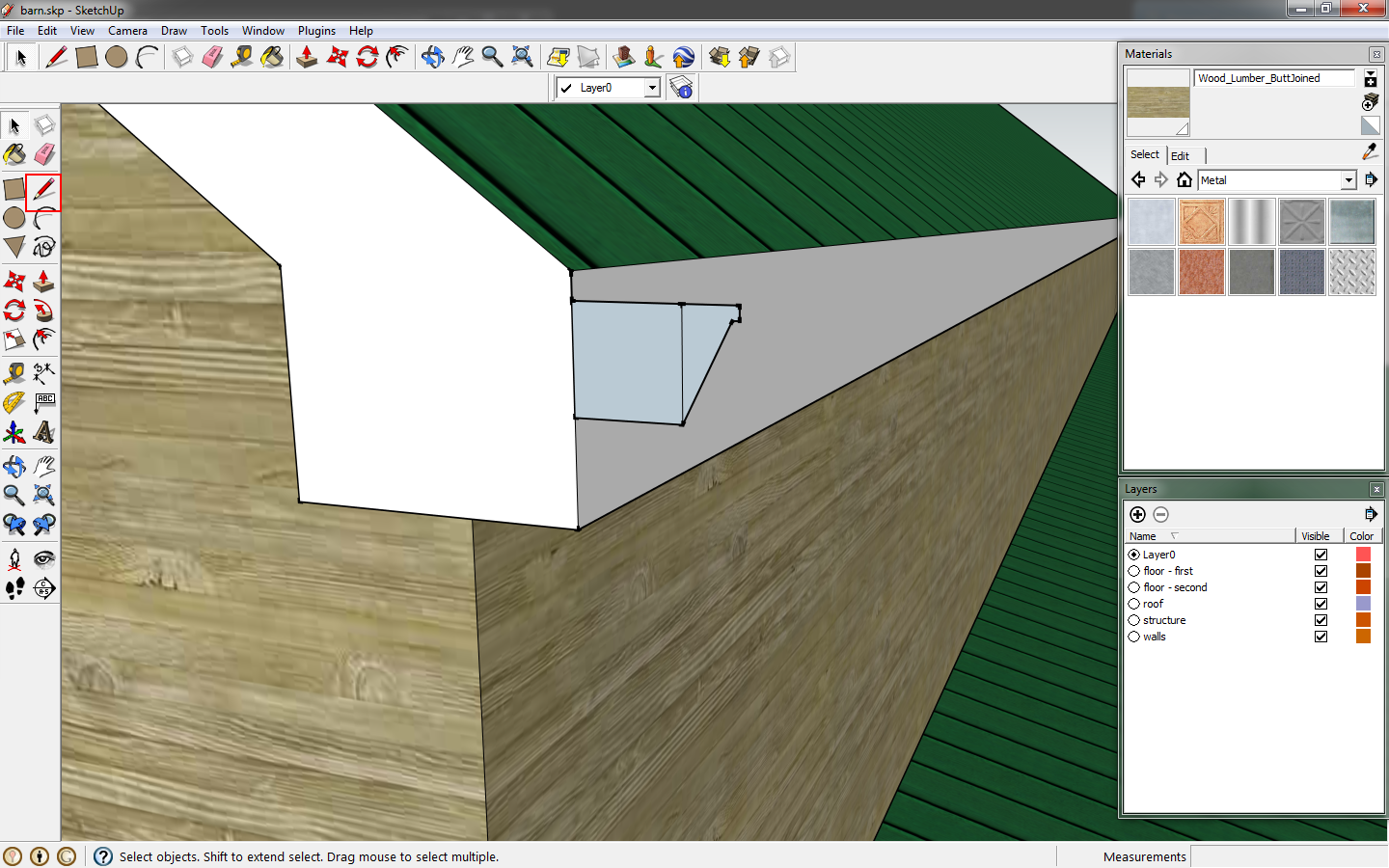 |
| Draw a gutter profile. |
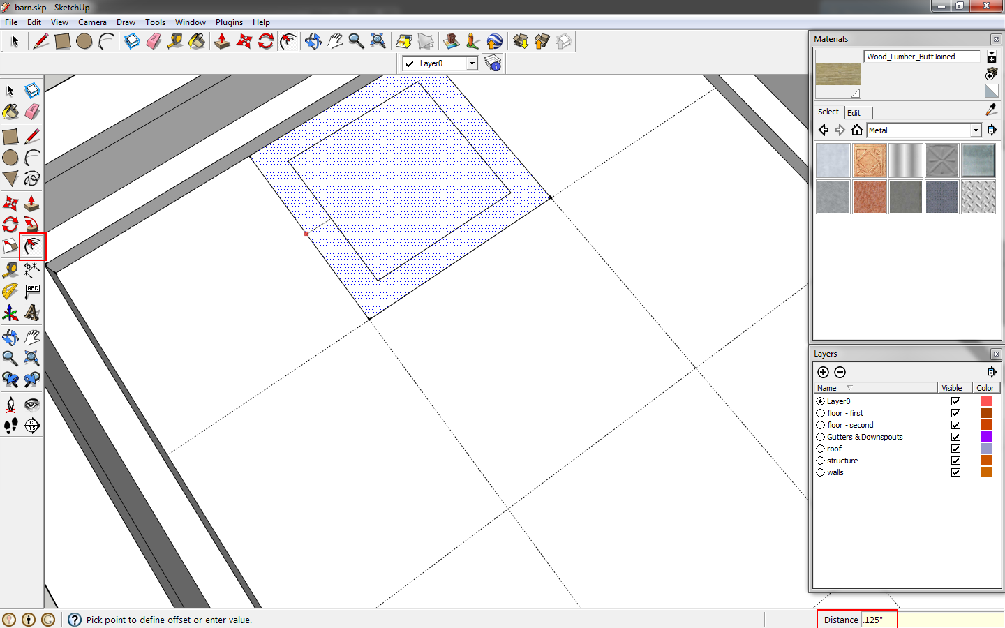
Click the face of the gutter, then use the
offset tool or key in
o. Click the perimeter of the gutter, move the mouse inside and key in
.125. Delete the lines to generate the gutter profile.
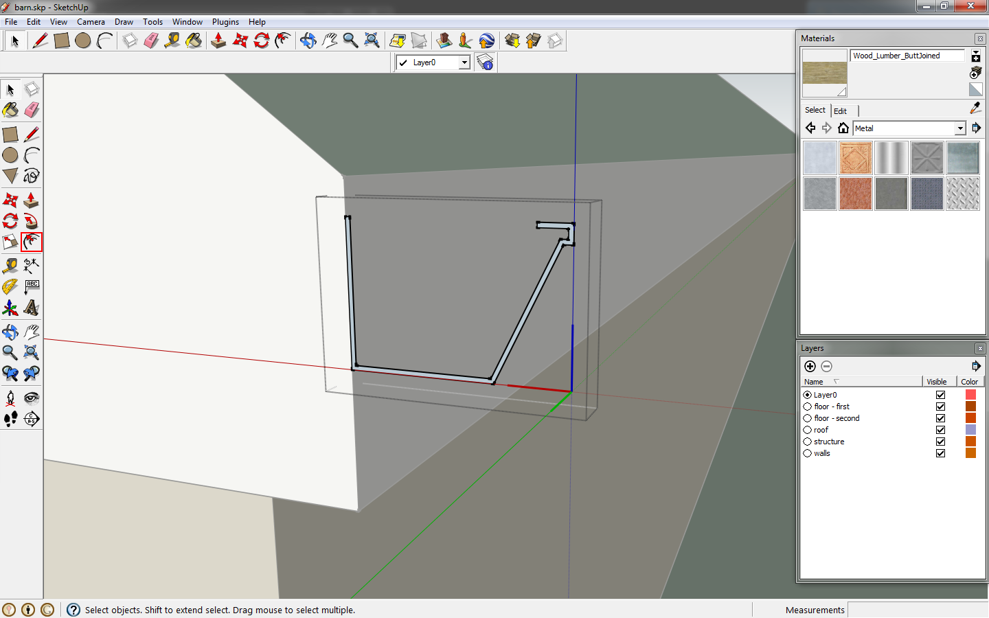 |
| Refine the gutter profile. |
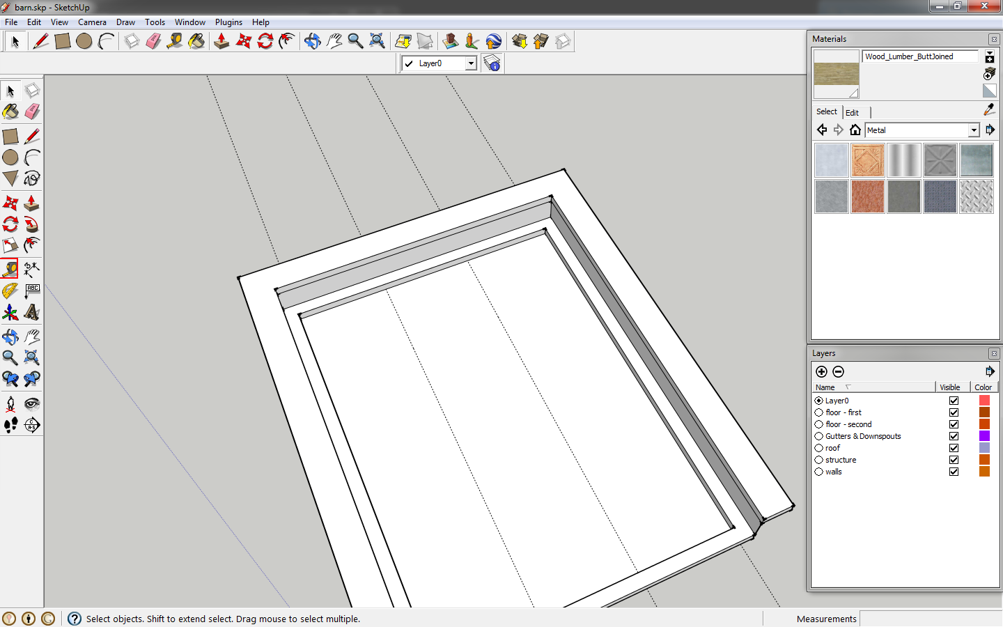
Use the
push/pull tool and click the gutter profile. If you hover the mouse on the far edge of the roof, the extrusion will lock to that edge. Click the edge and your extrusion will extend to that edge.
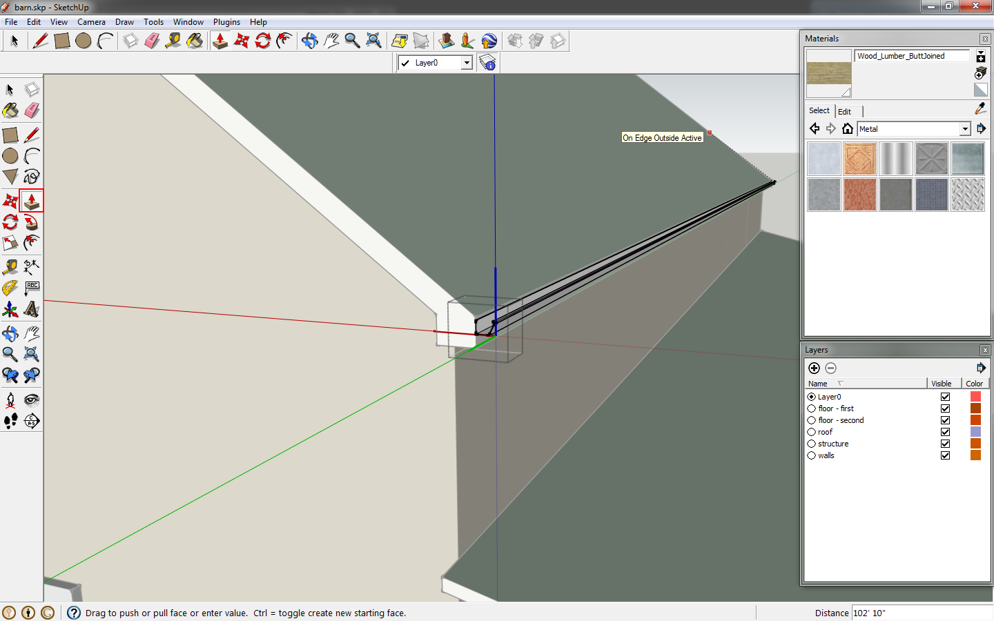 |
| Extrude the gutter profile. |
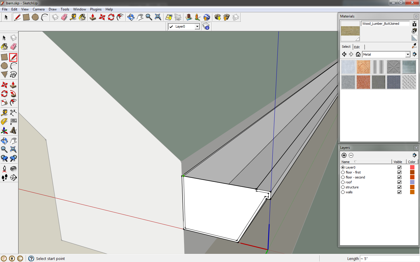
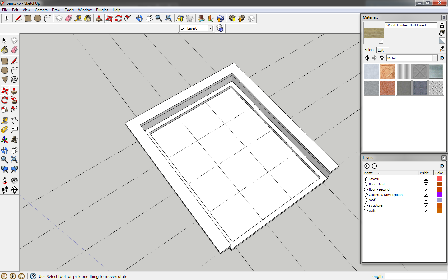
Draw a
line to close the end of the gutter. Delete the top face that results so that he gutter remains open.
 |
| Close the end of the gutter. |
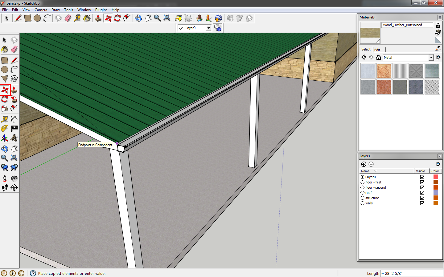
Finish editing the component. Click the gutter, click the
move tool. Click the roof corner as a reference point, click
ctrl to copy the gutter and move it to the shed roof.
 |
| Copy the gutter to the shed roof. |
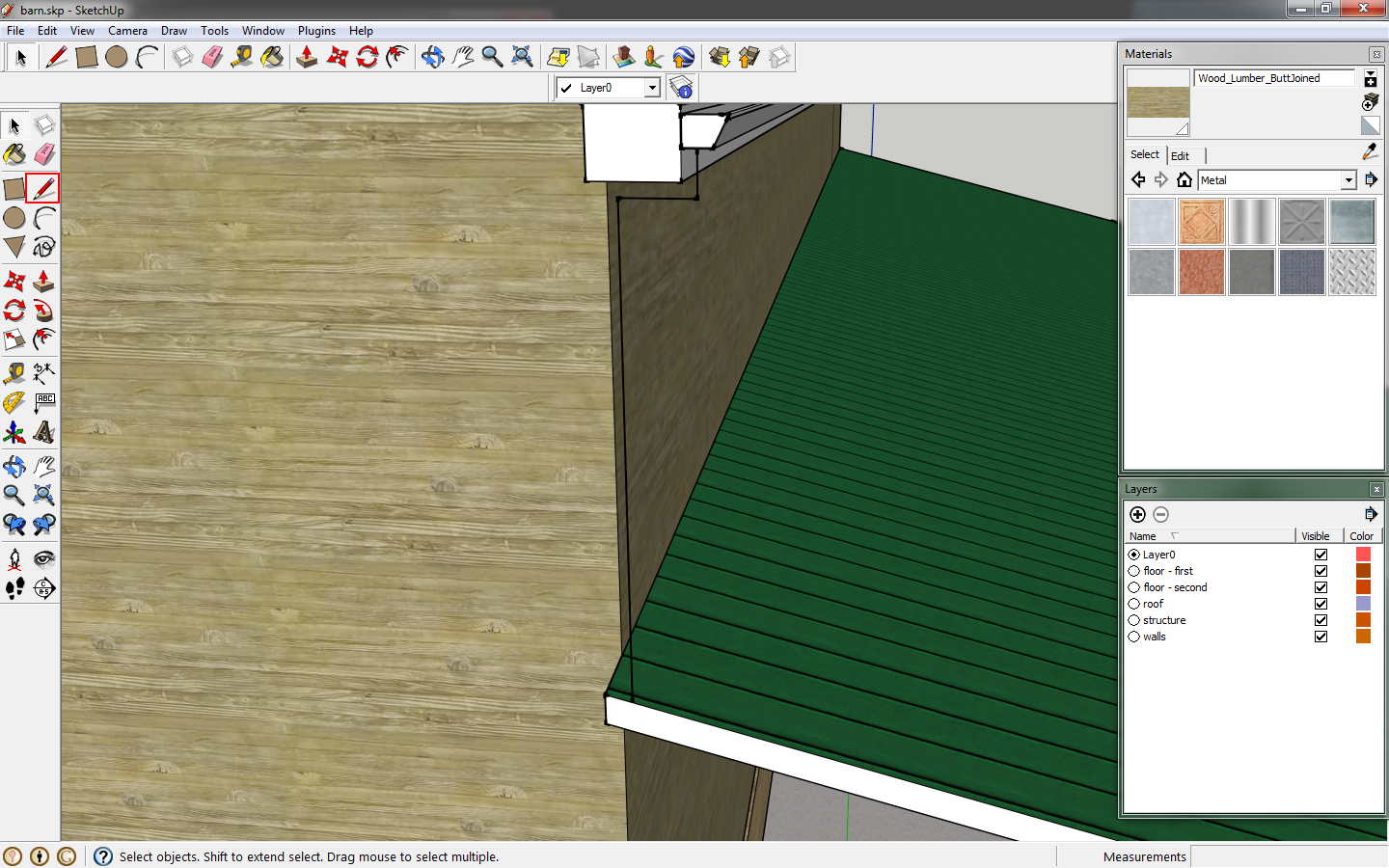
For the downspout, use the line tool to draw a rough path from the center of the gutter to the roof below.
 |
| Start the downspout shape. |
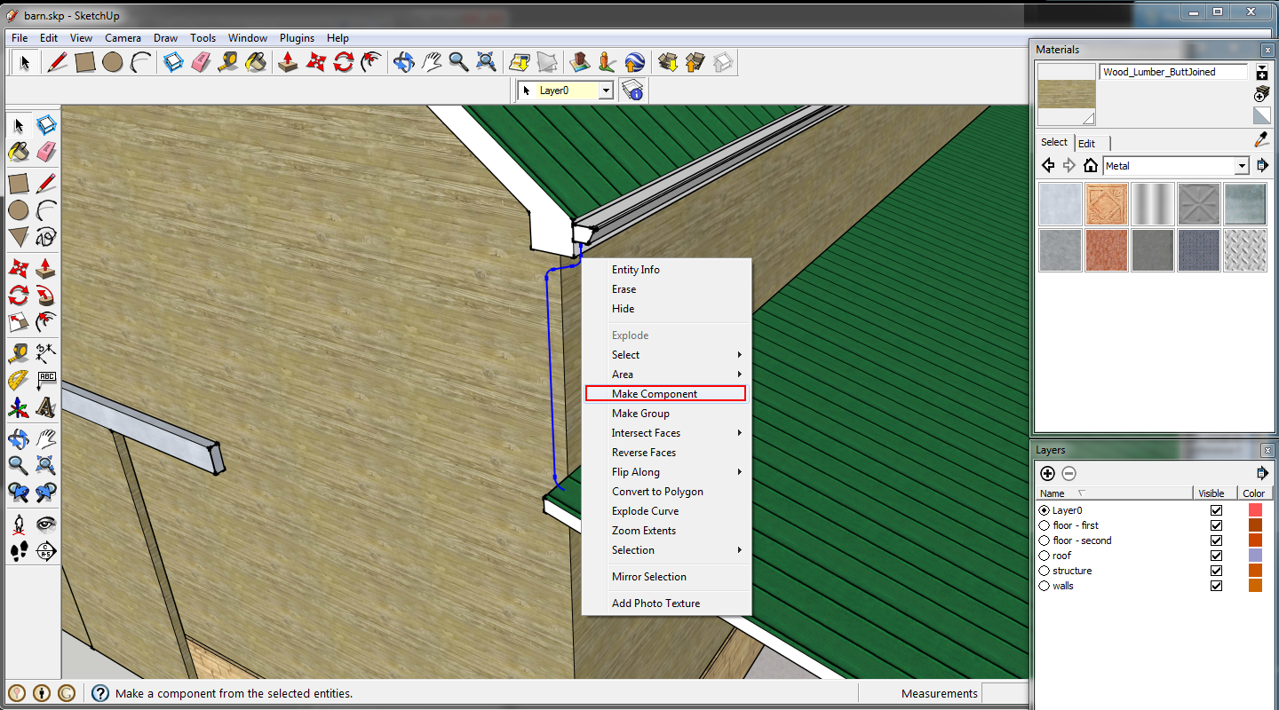
At this point, make the path a component. Components are awesome!
 |
| Make the outline a component. |
Draw a rectangle from corner to corner of your downspout sketch. This will help your downspout shape remain planar.
 |
| Draw a rectangle. |
Refine the downspout path, It should angle down slightly, with curves at the corners.
 |
| The downspout takes shape. |
Now we need a profile for the downspout. The nominal dimensions should be 3"x4". Use the guides,
tape measure tool or key in
t, to offset 1/2" lines to guide you in filleting the corners.
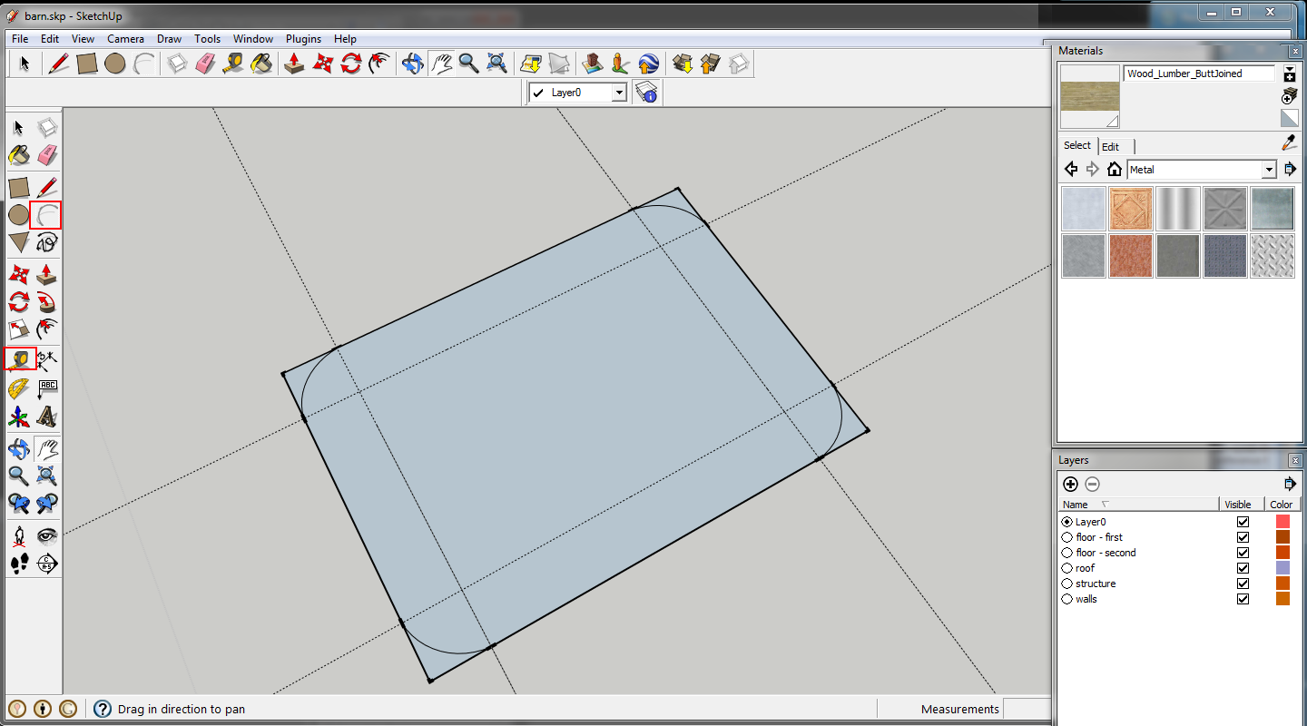 |
| The downspout profile. |
Move the profile to the edge of the downspout path.
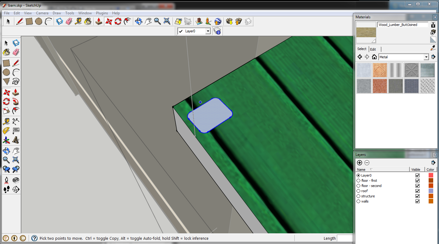 |
| Move the profile to the path. |
Select the path, click the
follow me tool, then click the profile. This should generate the shape. If not, click
follow me, click the profile and use the mouse to follow the downspout path.
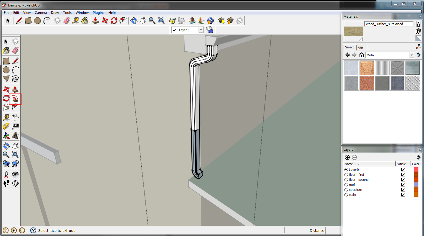 |
| Downspout created. |
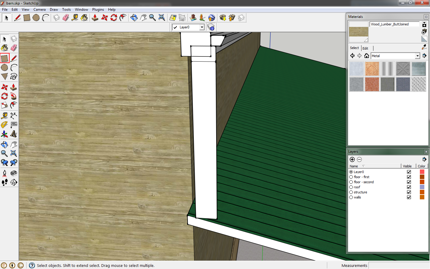
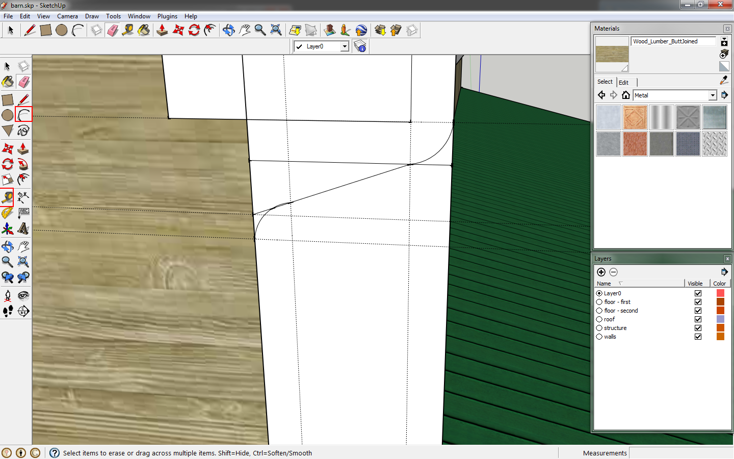
Use the
eraser tool and hold
shift to hide lines. The join line in the image below can be deleted. Lines along a curve should be hidden using the
eraser and holding
ctrl to soften edges.
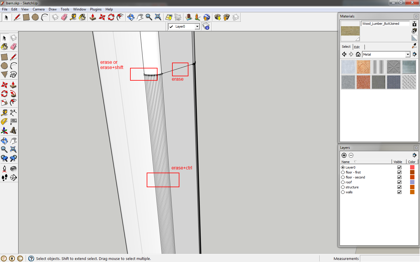 |
| Clean up the lines. |
Finish editing the downspout component. Move it off the edge of the gutter by 12". Next select it, click
move and hold
ctrl to copy it. Key in
20' and
enter. Immediately key in
5x to copy it five times.
 |
| Copy the downspout. |
Select one downspout and copy it to the shed roof. Right click this downspout and select
make unique. We will modify this component, but do not want to change all components. This creates a new component.
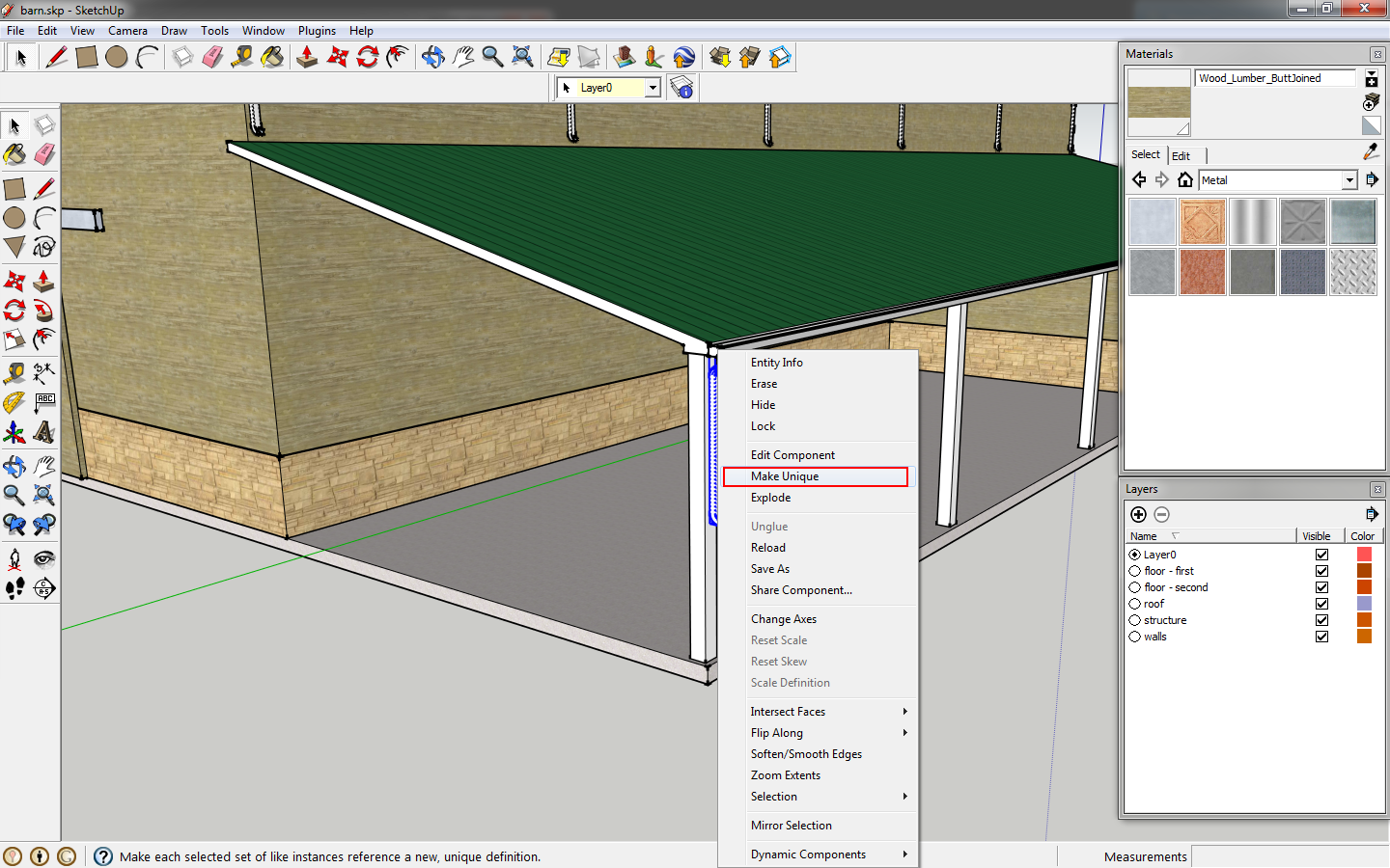 |
| Make the component unique. |
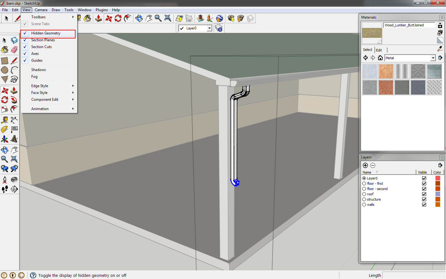
Go to the menu>
view>hidden geometry. You want this checked so that we select all elements of the downspout.
 |
| Turn on hidden geometry. |
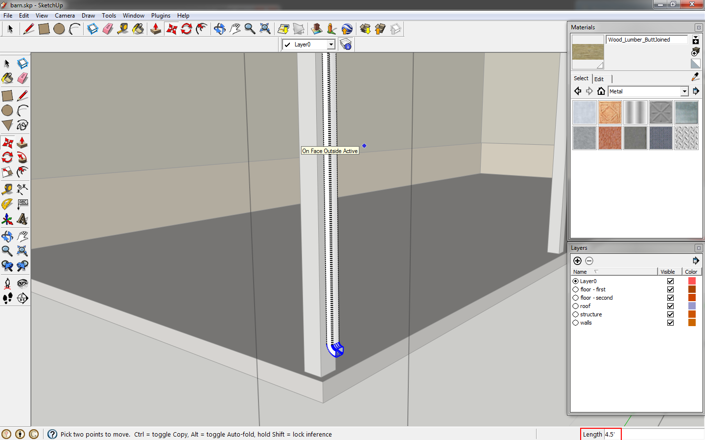
Select just the bottom portion of the downspout, click
move and key in
4'.
 |
| Extend the length of the downspout. |
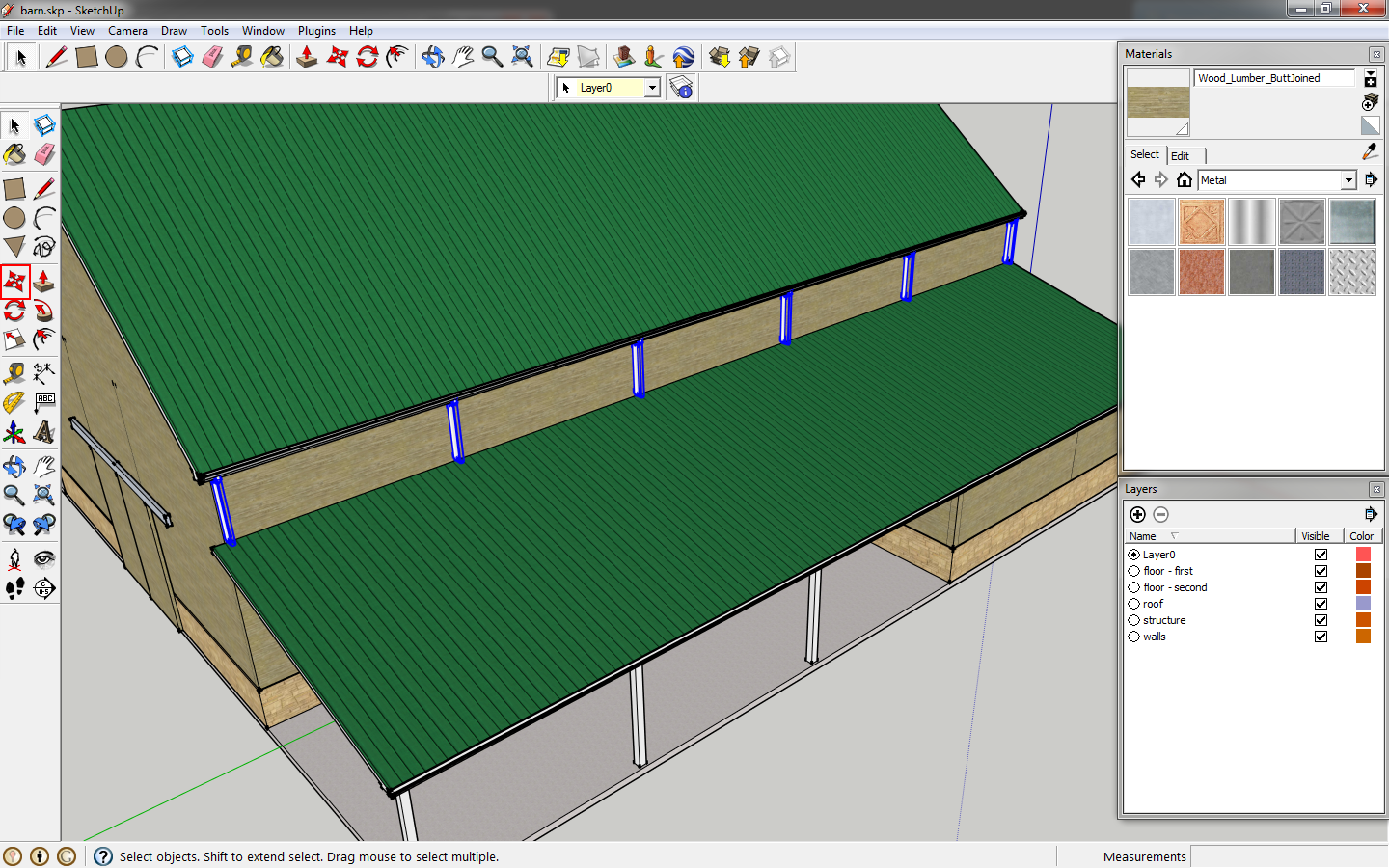
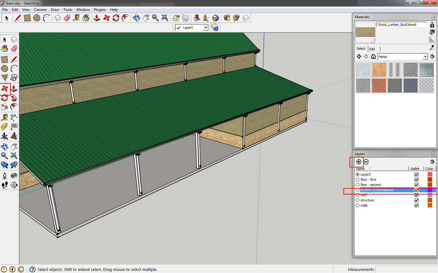
Copy this downspout five times, as we did for the downspouts on the upper roof. On the
layers window click to create a new layer and name it
Gutters and Downspouts.
 |
| Create a New Layer. |
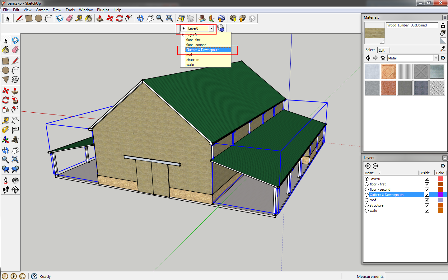
Then select your gutters and downspouts and put them on this new layer by clicking the drop down box at the top of the work area and selecting the new layer.
 |
| Place the items on the new layer. |
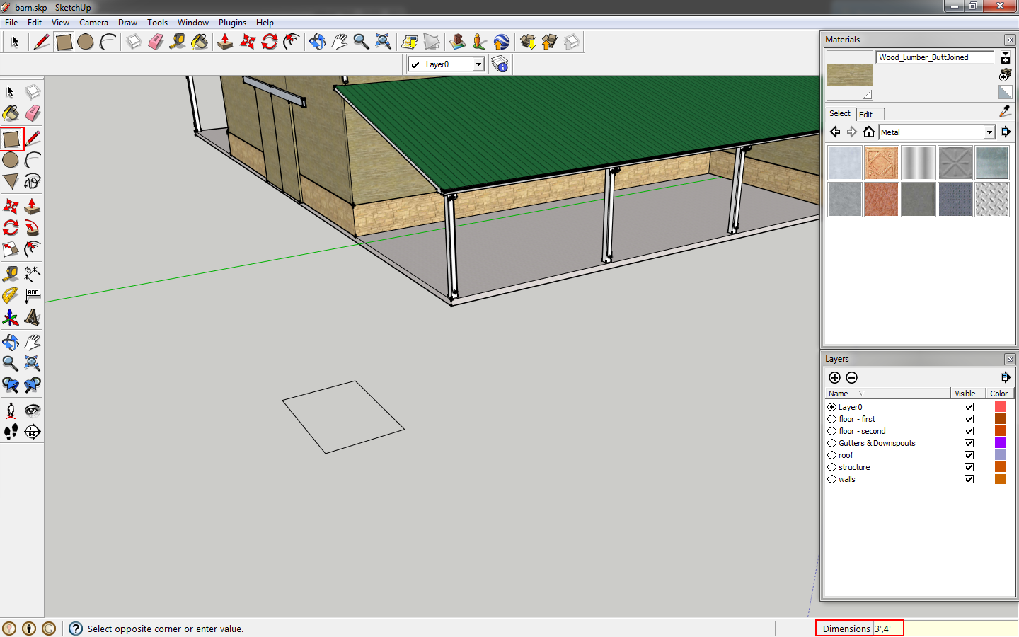
Now we need to add windows. You can check out Google's
3d Warehouse to find window models. Be sure to check the file sizes, as multiple large models can slow down navigation. We will draw a window from scratch. Start by drawing a 3'x4' rectangle.
 |
| Draw a rectangle for the window. |
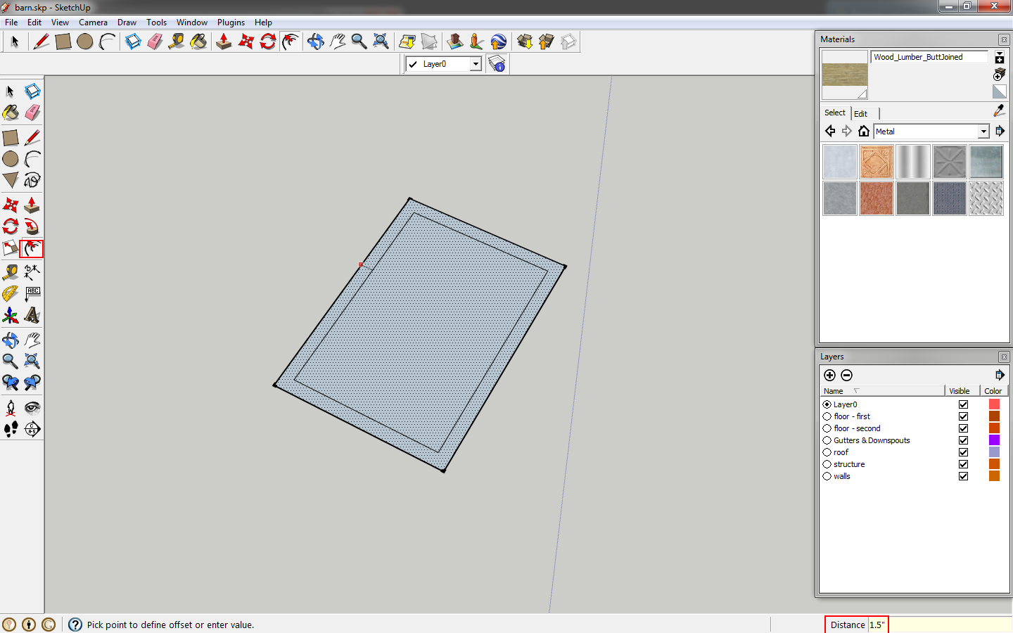
Select the face and offset it to the exterior of the rectangle by 1.5". This will be the window trim.
 |
| Add an offset for the trim. |
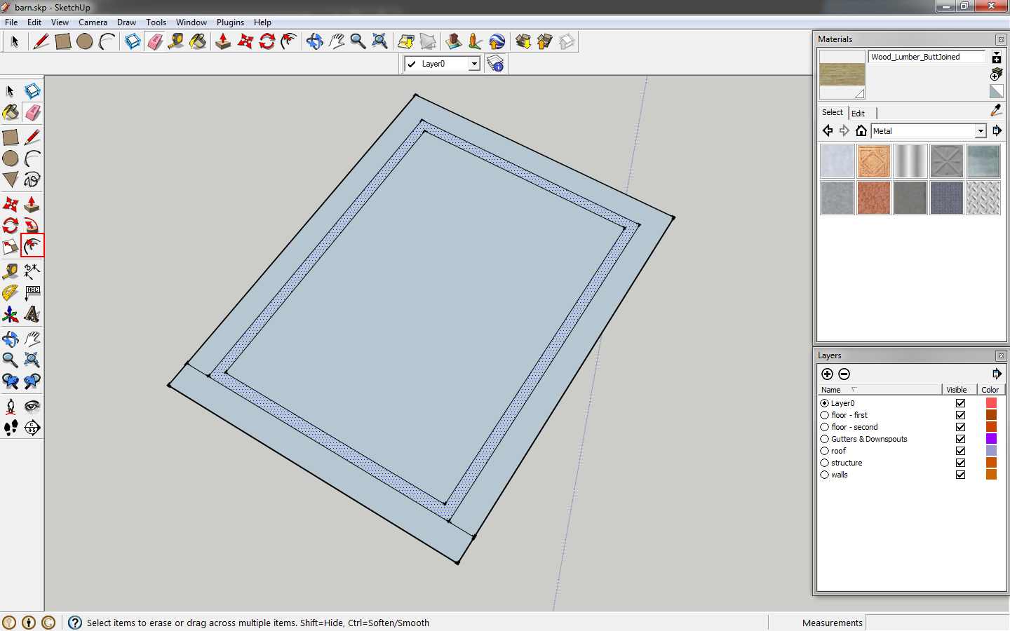
Offset the interior face by 1". Add a line across the bottom to delete that portion of trim.
 |
| Add another offset. |
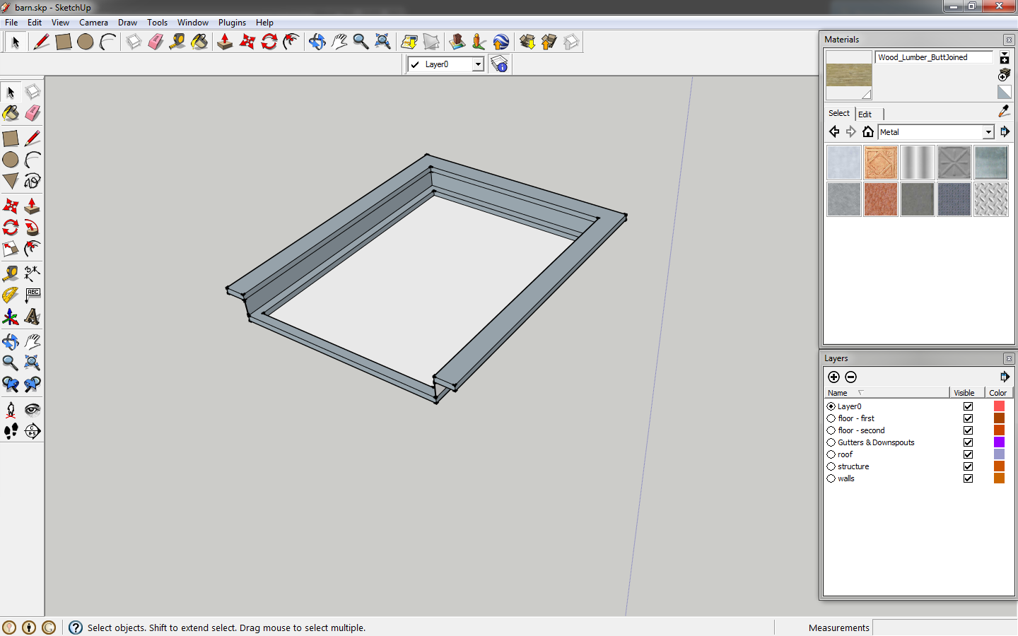
Extrude the trim by 6"and the window by 1". From the back extrude the trim by 5.5" to get the result below.
 |
| Extrude to shape the window. |
Create a vertical guide at one edge of the window. Select it and copy it to the other edge, immediately key in
/3 to separate the distance into three sections.
 |
| Place vertical guides. |
Do the same thing using horizontal guides, separating the space into four.
 |
| Place horizontal guides. |
Use the
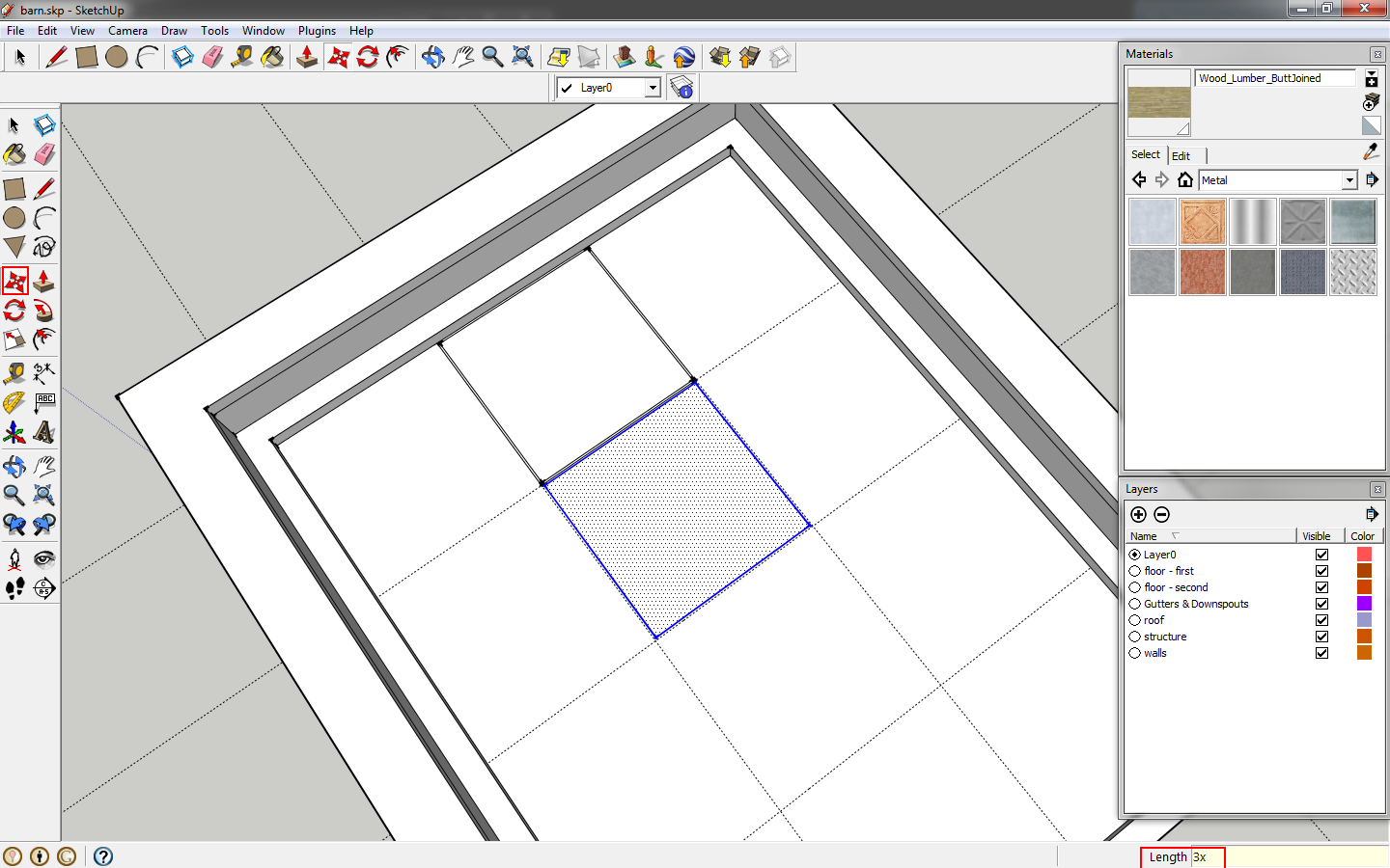
line tool to trace the guides, creating squares. Offset one square by .125".
 |
| Offset to create a window pane. |
Copy this pane to all of your boxes, using guides intersections as a base point.
 |
| Copy the panes. |
Delete the guides and the lines between your panes. Use
push/pull to extrude the muntins by .5".
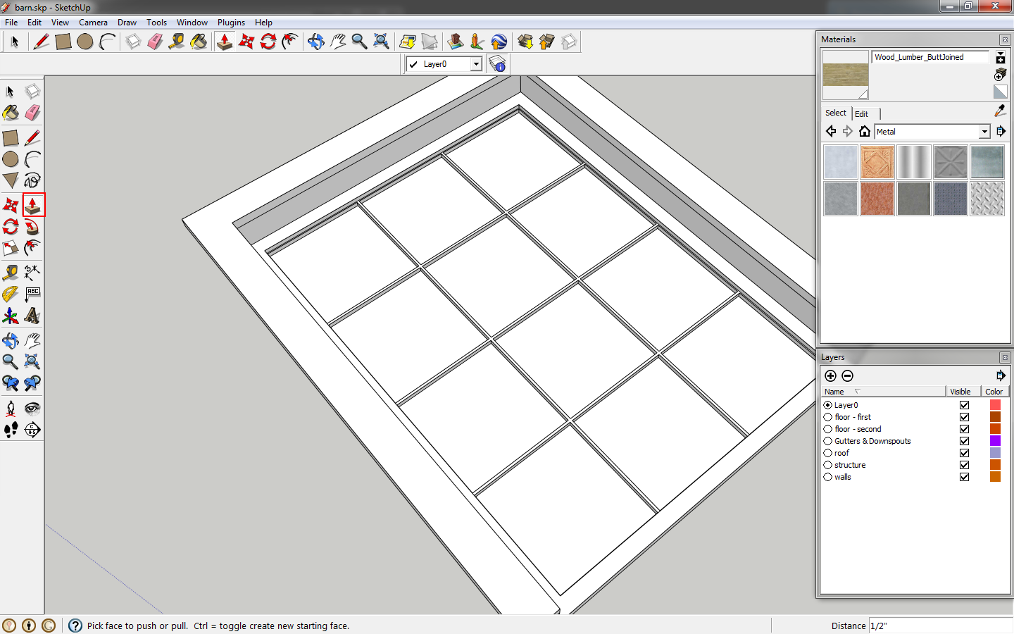 |
| It looks like a window. |
Click the
paint bucket tool or key in
b. In the
materials window, click the drop down and select
translucent.
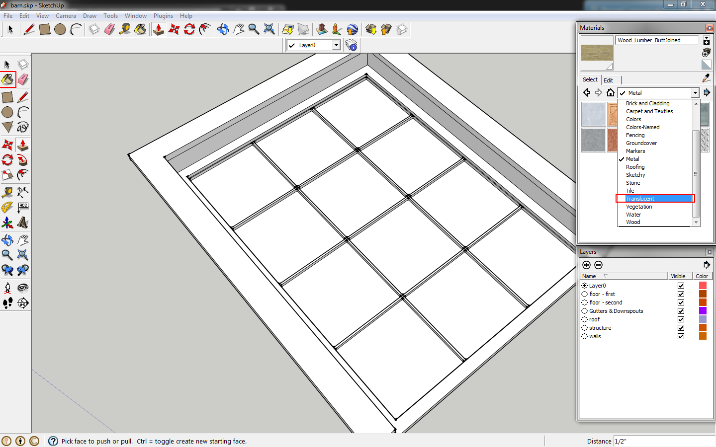 |
| Go to the materials window. |
Select
Translucent Glass Blue and click on each pane to apply the material.
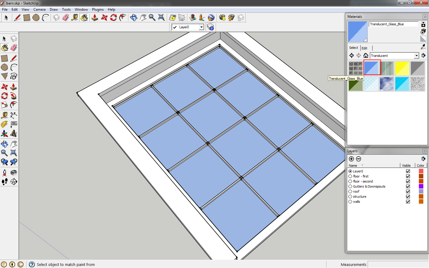 |
| We now have glass. |
Select all elements of the window and make it a component. Name it using the size, 3'x4'. In complex projects with lots of different window sizes, this makes it easier to select the right component.
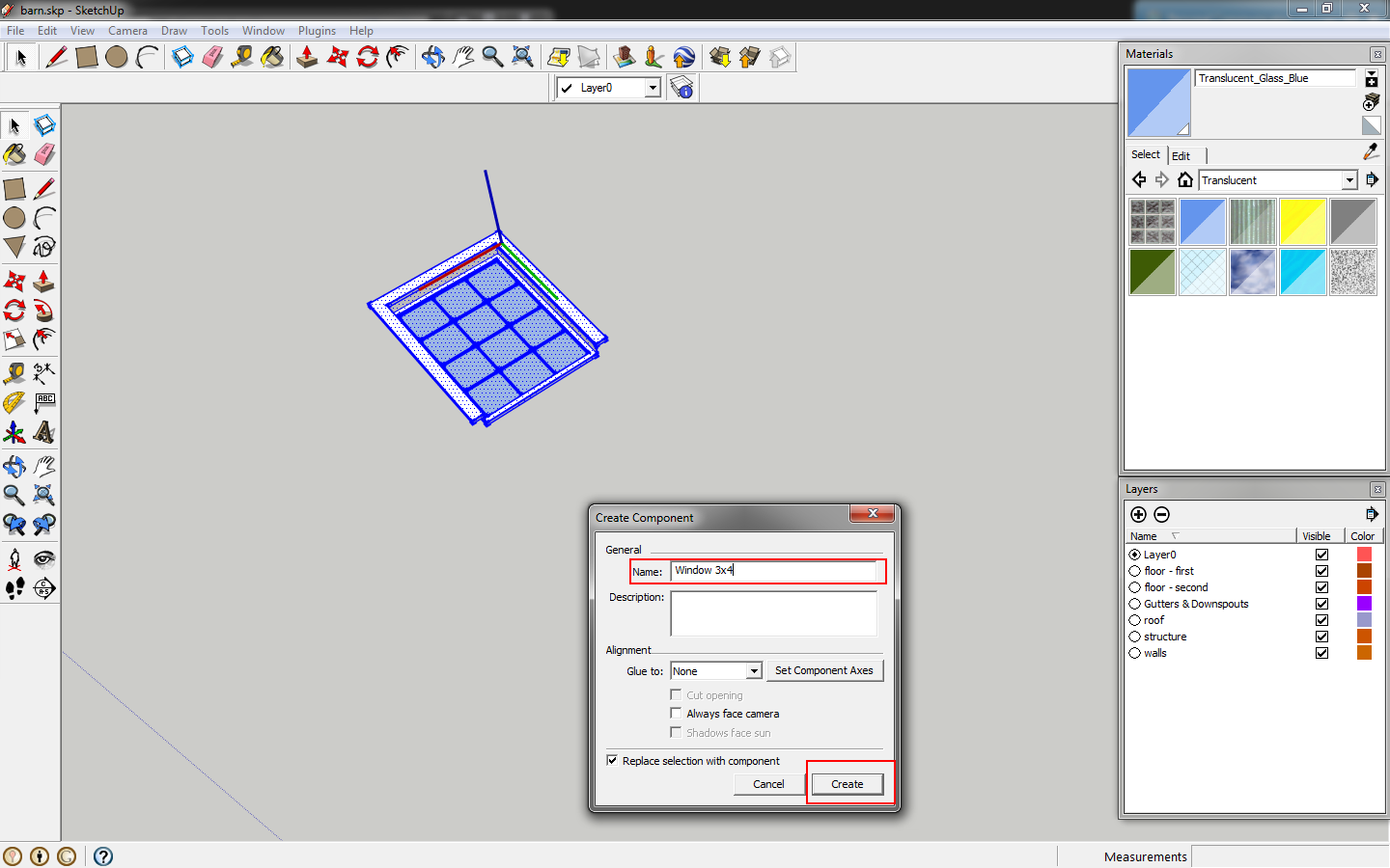 |
| Make it a component. |
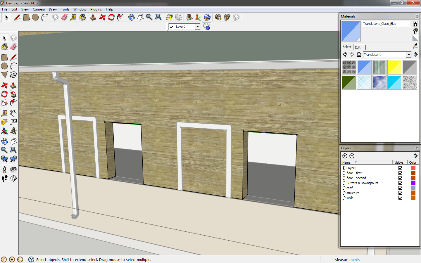
Move the window to the wall. It will rest on top of the stone base. You may need to rotate the window to be parallel with the wall.
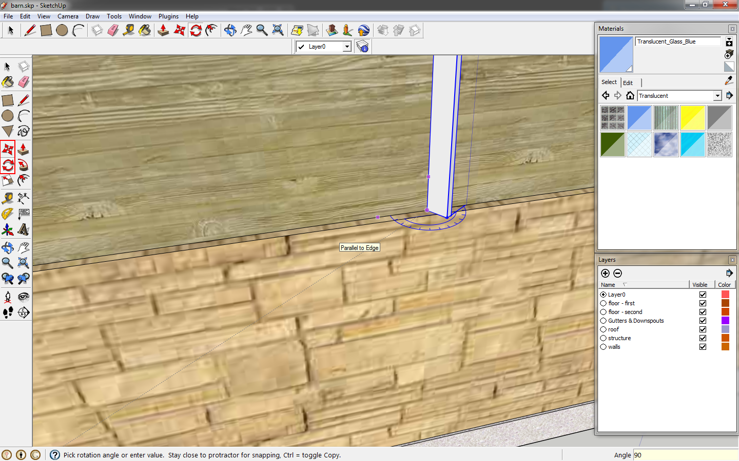 |
| Move the window to the wall. |
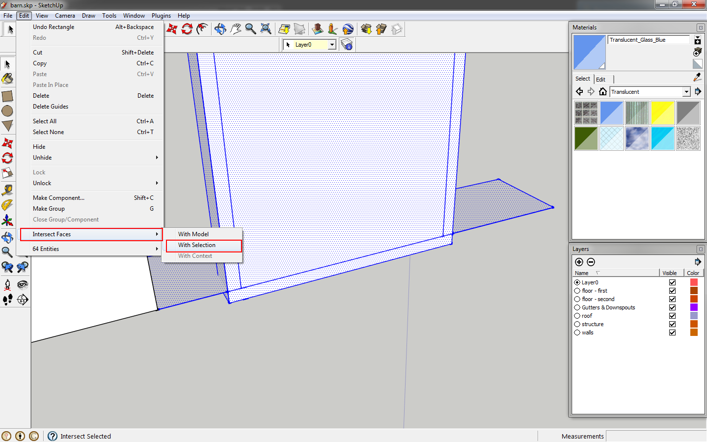
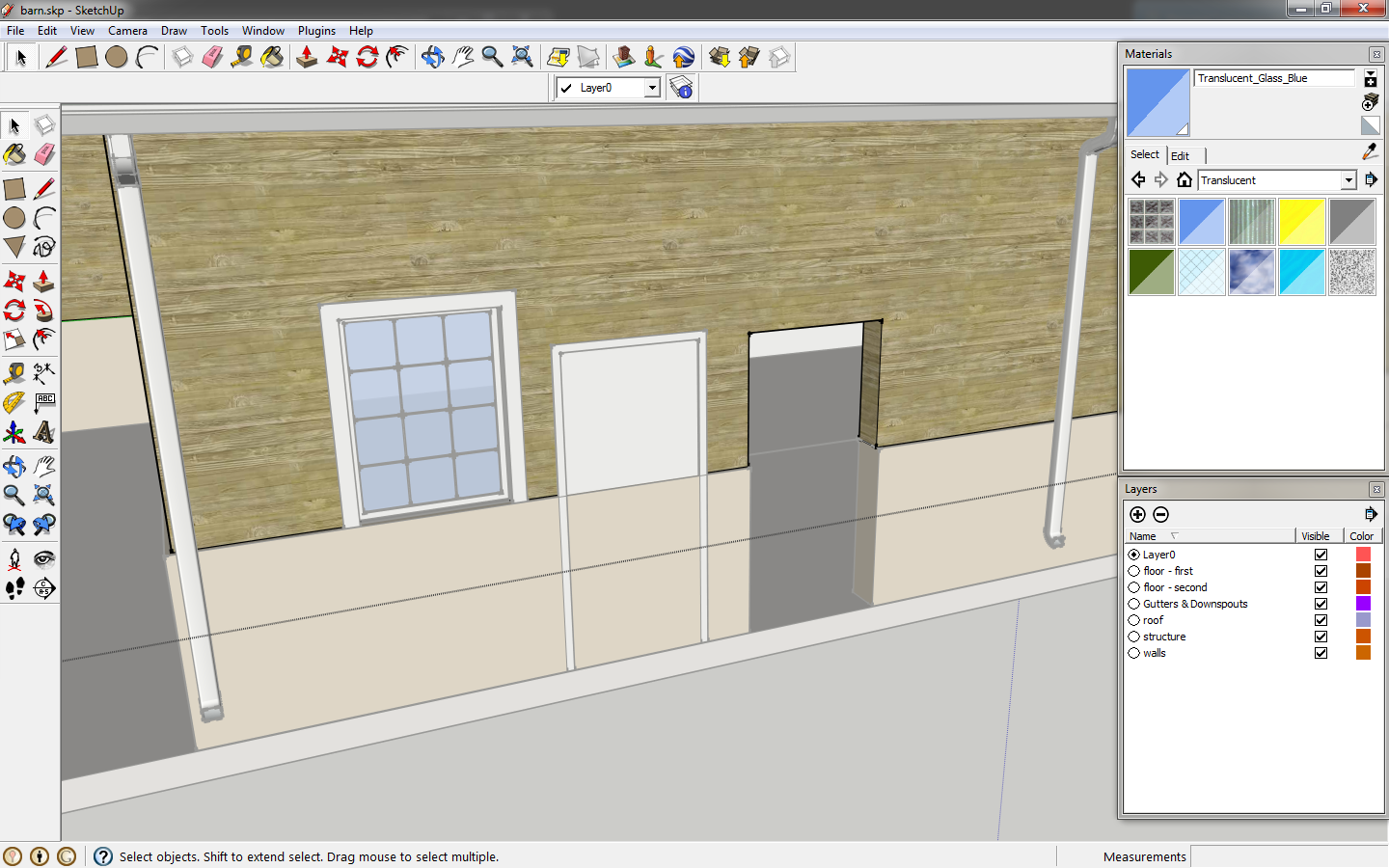
Select the window component and wall component. Right click and select
intersect faces>with model. This creates lines where the window intersects the wall.
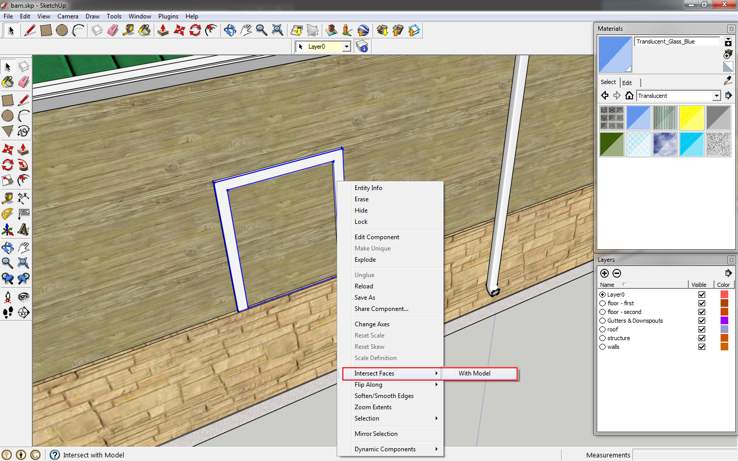 |
| Use intersect faces to create the window outline on the wall. |
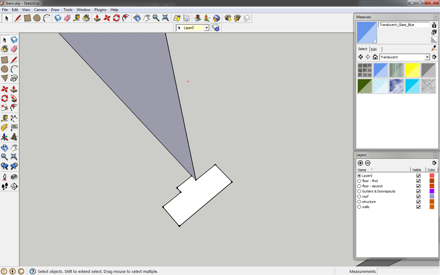
Move the window over 2' to reveal the created lines.
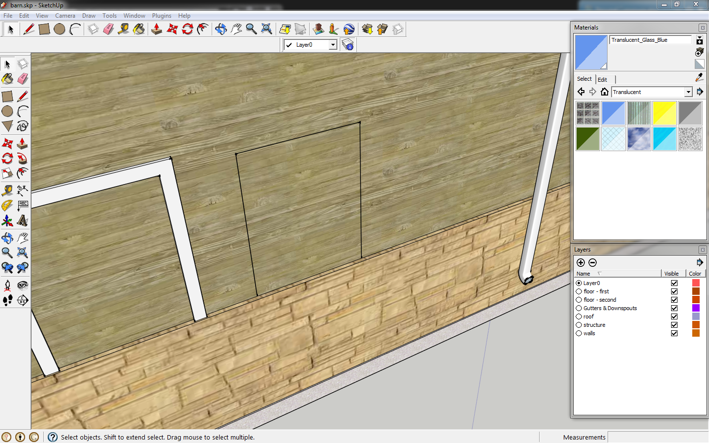 |
| Move the window. |
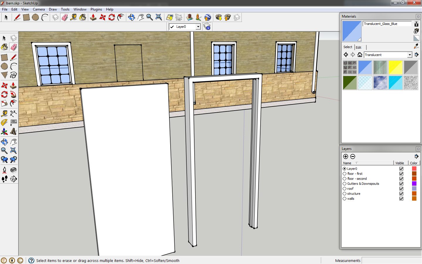
Edit the wall component, and draw a rectangle using the created lines as a guide. Then push the wall, 1/2" for the wood panel and again 8" for the structure to create the opening
 |
| Create the opening. |
Use the
eraser to remove any lines at the bottom of the opening.
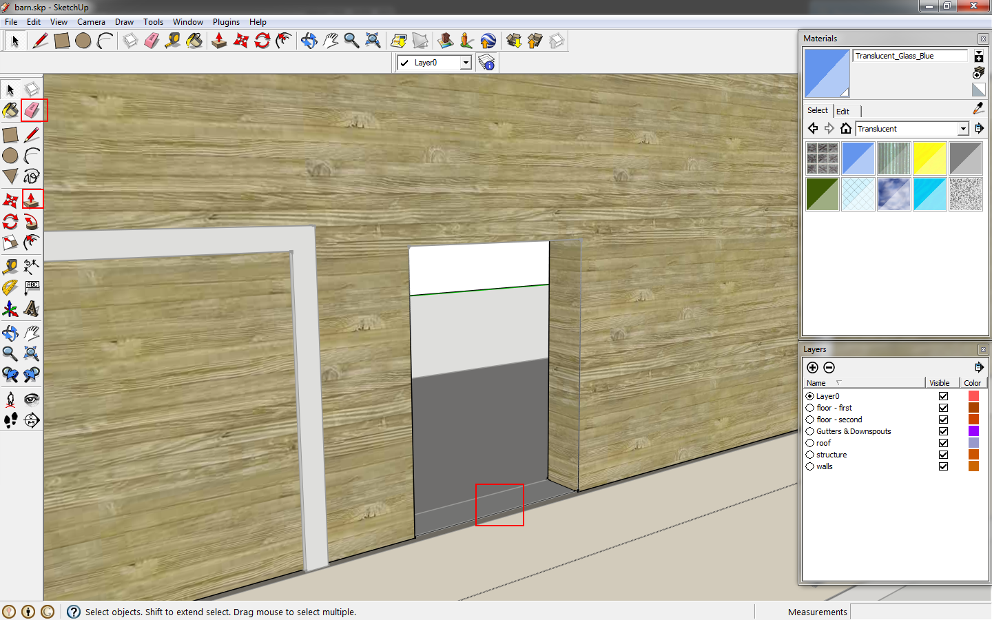 |
| Eraser the unnecessary lines. |
Add window opening as needed.
 |
| Create additional openings. |
Move you windows into the opening.
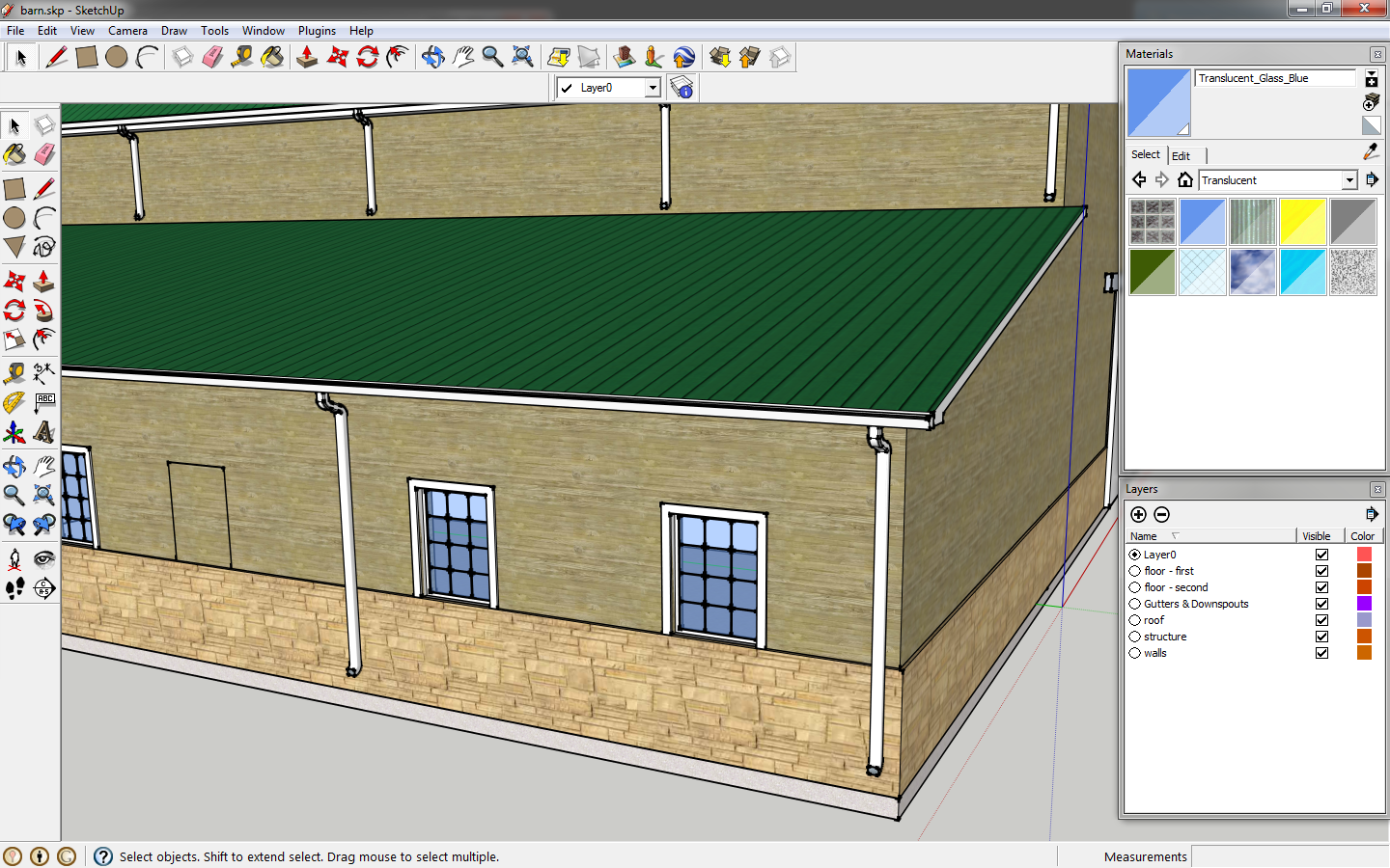 |
| Move the windows into the openings. |
We still need a man door. Start with a rectangle, sized 3'x7'.
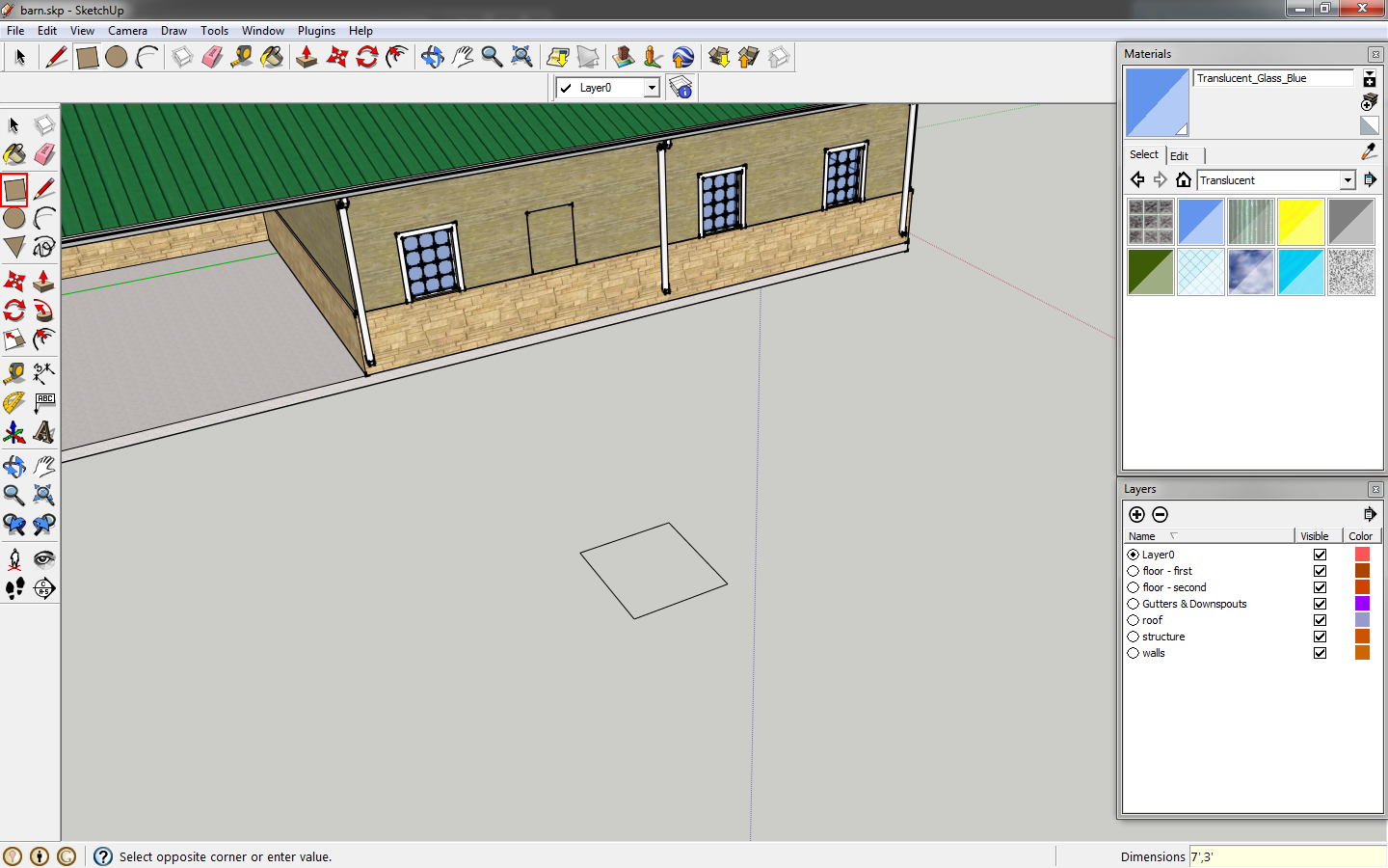 |
| Draw a rectangle. |
Extrude the rectangle 2"
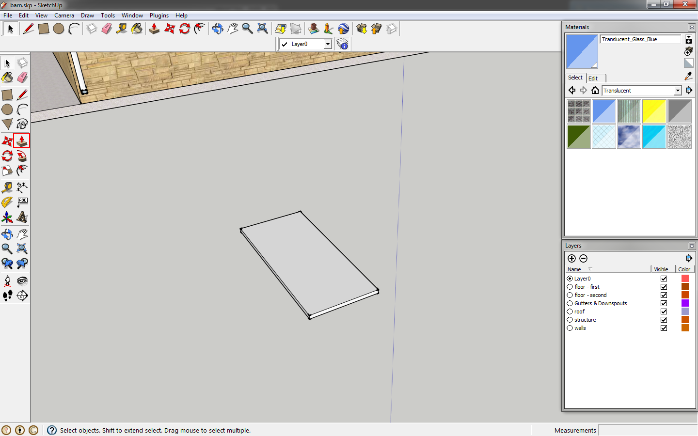 |
| Extrude the rectangle. |
Draw a frame profile, 2",6",2", 2.5",.5",1.5",.5",2". Also copy one face to the profile to use as an extrusion path.
 |
| Draw a frame profile. |
Click the 3'x7' face,
follow me, then the frame profile to generate the shape. Draw a rectangle at the base of the door and click
intersect faces to separate this part of the frame. The frame should stop at the floor plane.
 |
| Create the frame profile and delete the bottom portion. |
Delete the inner face of the frame. Make the frame a component and the door a component. This allows you to change door or frame components. With SketchupPro you can begin to animate the door opening.
 |
| The door and frame are done. |
Move the door into the frame and make that a component.
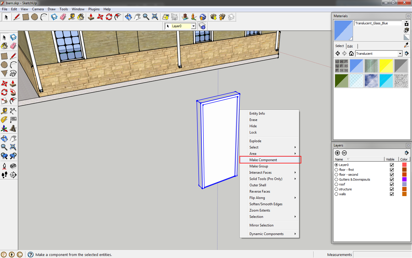 |
| Make the door and frame a component. |
Create an opening in the wall similar to what we did for the windows. You need to cut the wood paneled wall and stone base. The overall opening will be 3'4"x7'2".
 |
| Create an opening for the door. |
Move the door into the opening. Add a handle to the door to indicate swing direction.
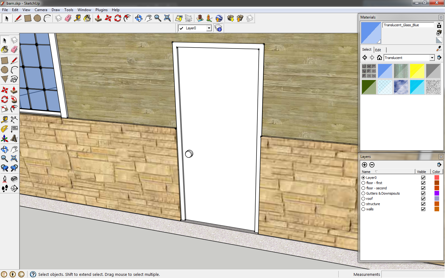 |
| Add a door handle. |
Now that the details are done, we will create scenes. Go to menu, select
windows>Scenes.
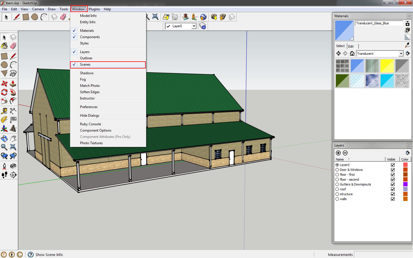 |
| Bring up the scenes window. |
Add a scene by clicking the
Add Scene button in the scenes window. Scenes are an easy way to see different facets of the model, saving which layers are on or off.
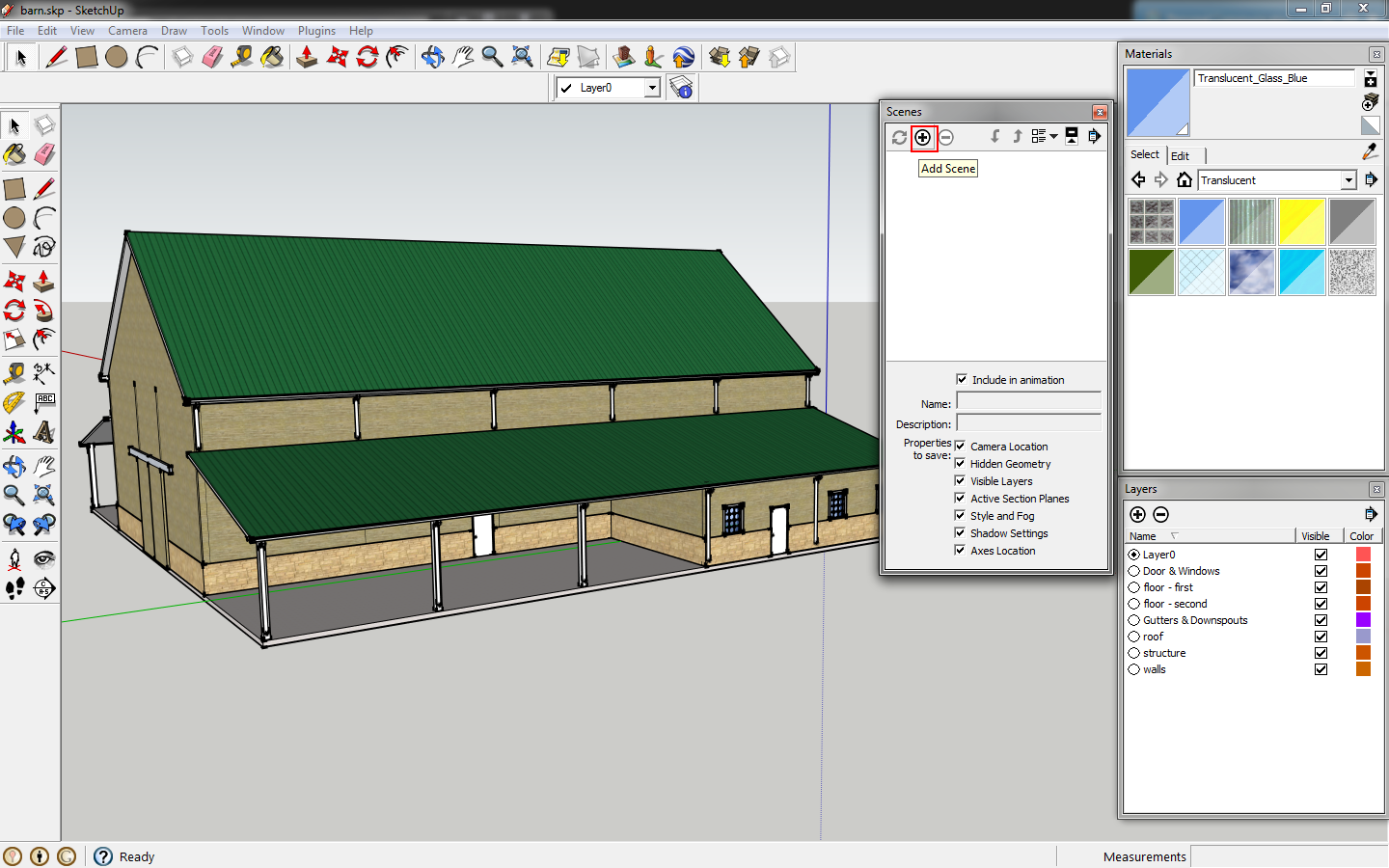 |
| Add a scene. |
My first scene is always title
working as that is where I turn layers on and off to modify the drawing. I don't want to change my plans and elevations once they are set.
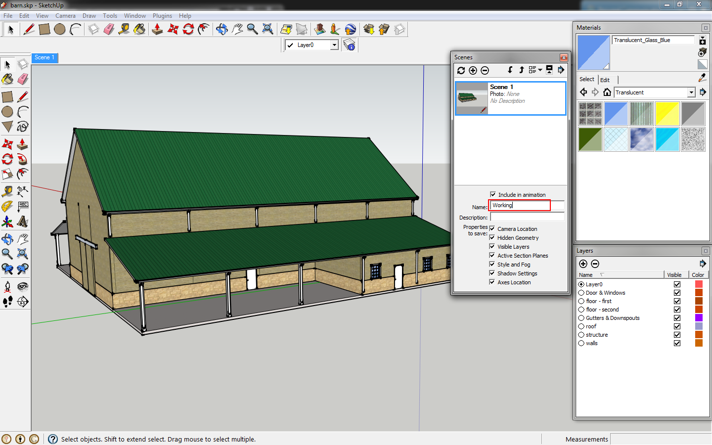 |
| Add a scene and be sure to name it. |
Add two more scenes,
First Floor Plan and
Second Floor Plan.
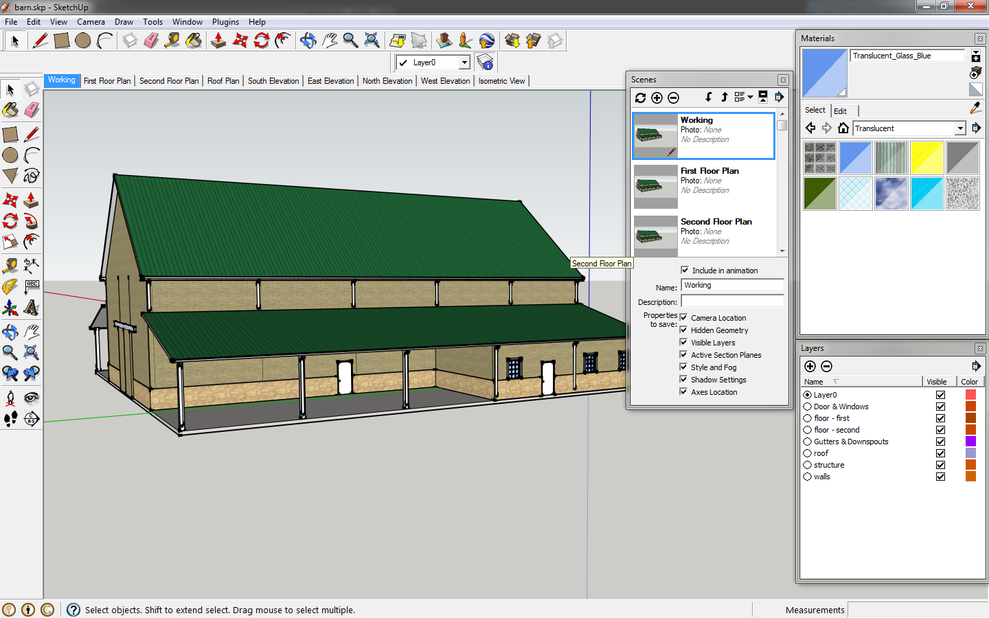 |
| Add more scenes. |
Go to the menu, access
tools.
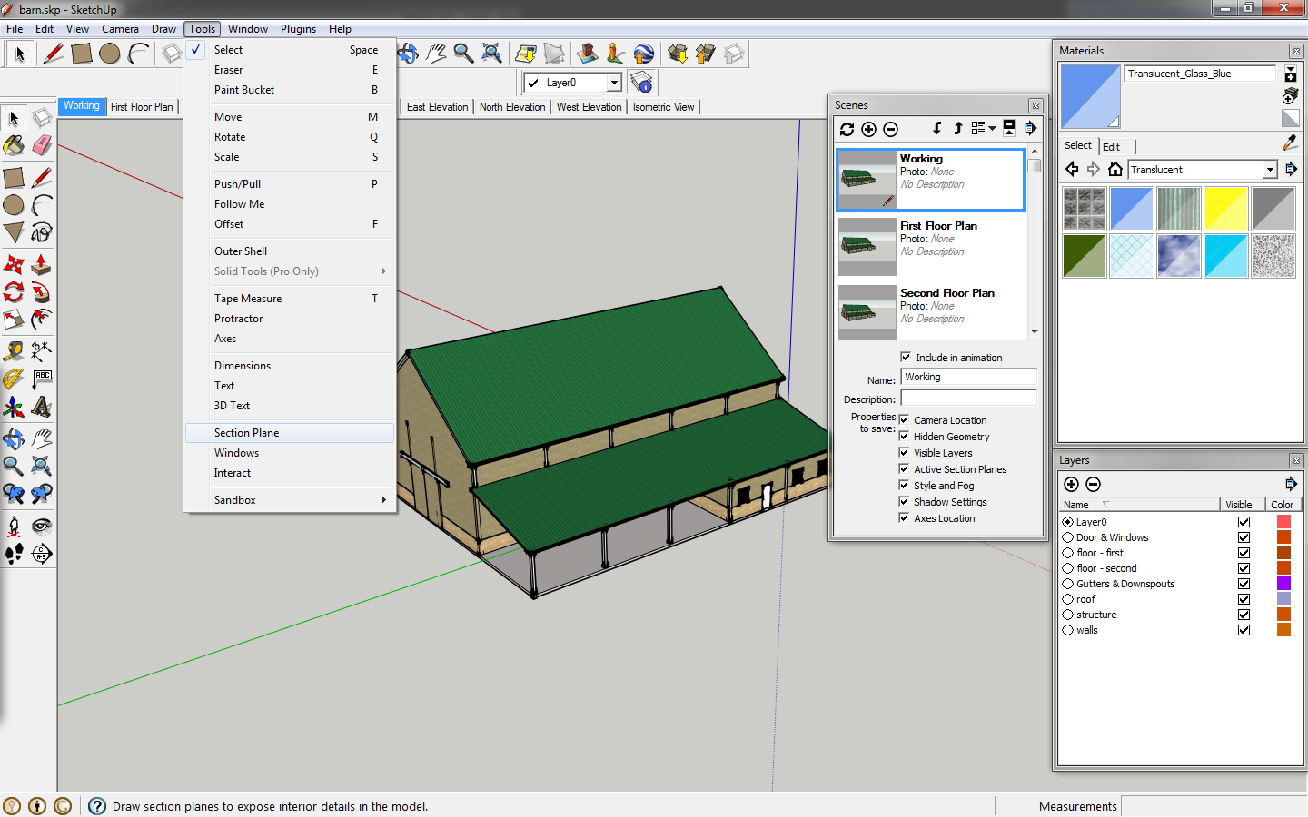 |
| Go to tools from the menu. |
Select
Section Plane.
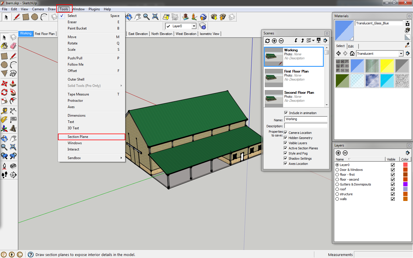 |
| Click section plane. |
We want to create a horizontal slice so we can see the floor plan. You can position the plane vertically by moving it.
 |
| The section plane. |
On the menu, click
camera>standard view>top.
On the menu, click
camera>parallel projection. If it is not already checked.
Turn off the
Axes and
Guides under
menu>view.
Right click the scene tab for
First Floor Plan and select
update to save the changes made.
Create a new layer,
Section Floor Plan 1. Move the section plane to this layer, turn the layer off, and update the scene again.
We will follow the same process for the second floor, moving the section plane higher, and creating a layer for that section plane. Update the scene.
Follow the process for the roof as well.
Create scenes for each elevation. Go to
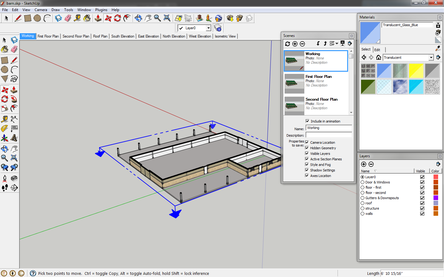
Camera>Standard Views. You want to click on front, back, left, right and update the scenes accordingly for each elevation. Make sure in the
scenes window that all the boxes for
properties to save are checked. Otherwise, they won't update with the scenes.
Also create an isometric scene. Isometric is a standard camera view.
With scenes, you can also save different styles. Go to
window>styles to bring up the
styles window. Select different styles such as marker, blue print, etc.
In this tutorial we added details and learned how scenes work.


No comments:
Post a Comment