

I started planning this build over three years ago, thinking I would start this project. I haven't, and it's not in the foreseeable future. The machine I want to build is $1700, and while that includes many things down to the nuts and bolts, it doesn't include everything. That cost is the main reason I haven't started this project.
I do want to build this project, and I recently glanced at my notes. My notes were scattered as I had ran calculations, revised calculations, updated the plan, and continued that process. In the moment, it made sense. Now it's a bit confusing. While my plan in Sketchup is quite exact, my notes as to how I derived that plan are less clear. I've gone back through my notes to clean them up for this post and figure out what I was thinking along the way so that when I do embark on this project I don't have as much to decipher. This is my guide, and I figure it might help someone else too. I have a lot of hours just in the planning.
Initial Design
I originally was thinking a 2'x4' cutting bed, but that got revised to 2'x2.5' for cost and size. The larger the bed, the stronger materials need to be to account for additional size which means more cost. I still don't know where I would put this once it (hopefully) is built.
At the end of this post is a nearly complete list of required components for the build.


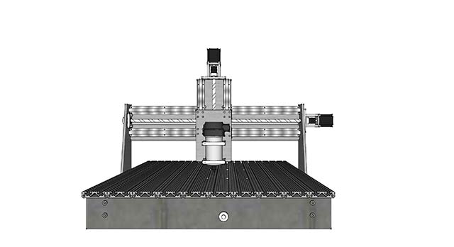
A CNC router is a Computer Numerical Controlled router. Instead of routing material by hand, a mounted router controlled by a computer can make exact cuts.
The router is mounted to a plate on rails that provides Z travel, up and down relative to the table top. The Z rails are mounted on a plate mounted to additional rails for Y travel, up and down horizontal to the table top. The Z rails, Y rails, and router make up the gantry. The gantry is mounted on rails that provide X travel, left to right horizontally across the table top.
Each plate/rail configuration is mounted to a ball bearing slide that slides across the rails smoothly. A threaded rod attached to the plate provides movement via a stepper motor connected to the threaded rod.
The motor twists the threaded rod and the mounted bearing moves the attached plate up and down the screw, moving the plate smoothly along the rails.
To actually cut anything with the router you need CAD software to model. Additional CAM software is required to translate the model to g-code to create tool paths to actually cut material, and to control the stepper motors.

Rails facilitate the path of travel. Each rail has two points of contact which keeps the axes moving
straight. Plates travel along the rails. The rails provide a precise path. The same plate has a bearing
connected to the ball screw which is in turn connected to a motor.
straight. Plates travel along the rails. The rails provide a precise path. The same plate has a bearing
connected to the ball screw which is in turn connected to a motor.

While profile linear rails are more precise than SBR round rails, they cost much more. It's $60 for
1000mm of SBR20 rail, $275 for profile rails. It's a good way to add a few hundred dollars to the
project (referencing Grainger and Walmart for prices).
1000mm of SBR20 rail, $275 for profile rails. It's a good way to add a few hundred dollars to the
project (referencing Grainger and Walmart for prices).
I will use SBR rails, which can also be mounted horizontally or vertically.
Motors & Mounting
The motor provides movement via the screw. The motor actually spins the screw.
The stepper motors are mounted to the frame via plate.
 I plan to use a NEMA 23, 280 oz motor. Here is motor size reference and a size estimator.
The stepper motors are mounted to the frame via plate.


The screw facilitates the movement with the driver attached to the screw.
I opted for ball screws over Acme screws. You can read a detailed ball screw primer highlighting
the pros of a ball screw.
Acme screws need an anti backlash nut. Backlash happens when a motor changes direction. Ball
screws are more efficient, very smooth and prevent backlash, less friction, and overall better than
acme screws. The anti-backlash nut increases friction further which taxes your motors.
Regardless of the type of screw you need a clamp and coupler to connect the motor to the screw. On
the other end you will need a bearing pillow block with a clamp.
 The longer the direction of travel, the larger diameter ball screw you need. I'm using 2505 and 1605
ball screws. The first number, 25 & 16, is the diameter with 05 being the pitch. A good rule of thumb is
16 mm diameter up to 24" and 25 mm for lengths greater than 24". You'll notice a C7 or C5 designation
with ball screws. This is the tolerance. The lower the number, the more precise.
I opted for ball screws over Acme screws. You can read a detailed ball screw primer highlighting
the pros of a ball screw.
Acme screws need an anti backlash nut. Backlash happens when a motor changes direction. Ball
screws are more efficient, very smooth and prevent backlash, less friction, and overall better than
acme screws. The anti-backlash nut increases friction further which taxes your motors.
Regardless of the type of screw you need a clamp and coupler to connect the motor to the screw. On
the other end you will need a bearing pillow block with a clamp.

ball screws. The first number, 25 & 16, is the diameter with 05 being the pitch. A good rule of thumb is
16 mm diameter up to 24" and 25 mm for lengths greater than 24". You'll notice a C7 or C5 designation
with ball screws. This is the tolerance. The lower the number, the more precise.
Software:
CAD software is required to draw the design. Sketchup has plugins to convert the model to g-code. CADBAM translate the CAD design to tool paths or g-code for the machine. I haven't tested the software, but this is the general plan.
Mach3 software is required for the controller for the motors.
http://www.instructables.com/id/Building-a-CNC-router/
http://www.instructables.com/id/DIY-CNC-Router/
http://www.cncroutersource.com/homemade-cnc-router.html
http://www.instructables.com/id/Build-a-Large-Space-Saving-CNC-Router-for-Under-60/
http://www.jonshobbies.com/first-diy-cnc-project-diy-cnc-router-part-1.html
The Build
I'm planning to use a lot of aluminum to keep this lightweight. Components need to be strong enough to withstand deflection, bending, and flexing. The flimsier components are, the less precise the machine is. To reduce deflection, heavier or thicker materials are required, but I also want to keep the gantry light weight. The heavier the gantry, the more the X axis rails could deflect. The gantry also needs to be balanced, distributing weight equally to the (2) ball bearing slides on each side.

Larger than this size, and I ran into deflection issues. My goal was a calculated .001" deflection as a baseline.
Everything is a trade off.
Rails and screws can get very expensive based on how precise they are. I'm using fully supported round rails. I like profile rails, but the price of rails for this would have been more expensive than the entire project.
I drew the plan in Sketchup and it was a lot of fun while being quite the process. I started with a lot of aluminum plate. I decided to use 3/8" steel plate on the short ends of the base as the weight should help ballast the machine. The long sides are 1530 extruded aluminum. I discovered t slotted extruded aluminum during the design. It's lightweight and rigid, perfect for this application. The thickness reduces flex, while the hollows keep it lightweight.
Cross bracing is 1020 extruded aluminum. Corner brackets will attach the 1020 braces to the 1530 sides. I debated on tapping holes, but wanted to avoid any conflicts with the rails while bolt to the other side of the aluminum.
Each bolt hole will have to be tapped.
For the gantry, I started with an 3/8" aluminum plate crossbar, verticals, and bottom bar. This keeps the weight down, compared to steel. Then I revised it to 3075 extruded T-slot aluminum crossbar to reduce deflection.
I calculated weight and deflections based on different sizes of the aluminum, aiming for low deflection and weight. It was an iterative process.
I wanted as a much Z travel as I could, but the more travel, the deeper the gantry rails, the more deflection, the more material needed to offset the height. I ended up with 5" Z-axis travel.
I debated on the work surface. I could use MDF or plywood for cost, but I like the tie down points extruded aluminum provides without screwing to the surface.
With the cost of the project, extruded 7530 aluminum isn't a big difference and it looks nicer than MDF while being stiffer. Deflection is always a concern.
Deflection calculator for extruded T slot aluminum
The work surface will cover the rails as much as possible to shield them from debris.
I decided to go 3” wide extruded for work surface after considering various sizes and running through calculations.
I will use an MDF scratch board when needed.
I'm planning to use SBR20 rails for the X-axis, SBR16 rails for the Y-axis, and SBR12 rails for the Z-axis. The size difference is due to the fact that each axis is a different length. With each rails are (4) linear ball bearing blocks SBR20UU, SBR16UU, SBR12UU.

I'm using a RM2505 ball screw for the X-axis and RM1605 ball screws for the Y-axis and Z-axis. The ends need to be machined so that a coupler can attached the ball screw to the motor. I'm using Oldham couplers.
For the ball screw end opposite the motor, a bearing is needed to reduce friction. A collar is fitted on the end of the ball screw.
With the motors, I selected NEMA 23, 280 oz motors based on research.
Once I was happy with the design, I went back to reduce the number of differently sized bolts. With the first few rounds of design, I selected what seemed right, but using fewer sizes will save cost.The extruded aluminum has holes in each end which helped determine bolt diameters. The holes will need to be tapped.
I did a lot of calculations on the gantry for deflection and weight balance. Weight balance is why the gantry side plates have an angle to them. You want the gantry to ride on the sliding blocks evenly
Gantry Calculations
Rough weights:
Aluminum: 0.101 lbs/in³
Steel .2833 lbs/in³
Sbr16 - .0559 lbs/in
SBR16UU- .326 lbs
SBR20- .0599 lbs/in
SBR20UU- .481 lbs
SBR12- .0519 lbs/in assumed
SBR12UU- .192 lbs
Stepper motor 2.2 lbs
Bearing: .09 lbs
Router 8.2 lbs (Bosch Colt)
Calculations: X axis deflection - load weight
Gantry
| ||||||||
Item
|
Bottom plate
|
Side plates
|
Cross plate
|
Sbr16 rail
|
Sbr16 uu
|
Pillow block
|
Spindle plate
|
Spindle collar
|
size/#
|
6x29x.5
|
67.68in^3 (x2)
|
6x28x.5
|
28” (x2)
|
x4
|
2.5x4x.25 (x2)
|
5x9x.5
|
3.5x3x.5
|
Lbs x
|
.101
|
.101
|
.101
|
.0559
|
.326
|
.101
|
.101
|
.101
|
weight
|
8.787
|
13.671
|
8.484
|
3.13
|
1.304
|
.505
|
2.272
|
.530
|
Gantry cont’d
| |||||||
Item
|
Pillow block
|
Sbr12 rail
|
Sbr12 uu
|
Shaft plate
|
Stepper motor
|
bearings
|
spindle
|
size/#
|
2.5x4x.25 (x2)
|
8 (x2)
|
x4
|
2x4x.25
|
x2
|
x4
|
x1
|
Lbs x
|
.101
|
.0519
|
.192
|
.101
|
2.2
|
.09
|
8.2
|
weight
|
.252
|
.8304
|
.768
|
.202
|
4.4
|
.36
|
8.2
|
I computed the weight of each piece of the gantry with the total Gantry Weight coming in at 53.695 lbs.
That's a .0058” deflection with 1020 alum extrusion. To get the 1020 deflection down to .0018”, I would need just a 20lbs load.
With 1030 extrusion deflection is .003". With a 2040 extrusion deflection is .0009”. With 1530 extrusion deflection .0008”.
With two extrusion rails, each assumes half the weight. At half load deflection is .0006” with 1530 extrusion.
This deflection does NOT account for material.
Plywood: 3/4" 2x3’ piece- 12.78 lbs
Solid surface: 2x3’ piece - 25.2 lbs
Aluminum: 24x36x.5 - 43 lbs //.25” 22 lbs - I'm unlikely to route a full piece of aluminum
Calculations - Gantry Deflection
The gantry was originally aluminum plate, but that had a lot of deflection.
I calculated deflection for the extrusion profiles.
Under heavy load the 1545 extrusion is fine. But the extra width pushes all my components forward.
The 3034 extrusion is great on deflection and less wide. I opted for two of those for the back of the gantry.
Gantry Center of Gravity
Formula is distance from end point multiplied by the weight to get foot-pounds of force
Add up total foot-pounds and divide by total distance to get the center. I converted to inch pounds
due to the relative quantities.
Centering the gantry weight prevents rocking issues and even weight distribution is optimal for efficiency.
Weight are listed a couple sections above in this post.
due to the relative quantities.
Centering the gantry weight prevents rocking issues and even weight distribution is optimal for efficiency.
Weight are listed a couple sections above in this post.
Side plate
|
Back plate/cross
|
bearing
|
Y plate
| |
weight
|
3.68
|
8.484
|
1.304
|
3.03
|
distance
|
2.47
|
.25
|
1.625
|
2.5
|
inch/pounds
|
9.105
|
2.121
|
2.119
|
7.575
|
Z rail
|
bearing
|
Spindle plate
|
Spindle collar
|
spindle
|
0.8304
|
0.768
|
1.76
|
.82
|
8.2
|
3.125
|
3.1825
|
4.625
|
6.875
|
6.875
|
2.595
|
2.928
|
8.14
|
5.6375
|
56.375
|
Stepper motor
|
Drag chain angle
|
totals
| ||
2.2
|
1.069
|
34.206
| ||
3.625
|
-.718
| |||
7.975
|
-.767
|
106.918
|
=106.918/34.206
3.103 inches to COG from back side of gantry. With a 6" wide gantry, this is pretty spot on.
I toyed with the size of the triangular cutouts on each end to zero in on the perfect center gravity, plus since I don't have a router yet that could alter things.
I toyed with the size of the triangular cutouts on each end to zero in on the perfect center gravity, plus since I don't have a router yet that could alter things.
The extruded aluminum cross brace, drops 2lbs of weight which hurts the COG
Weight of 3075 is .1157 / inch - 3.268 x 2// 2.451 inch/pounds. That hurts balance slightly
The updated center is 2.47” from the back of the side plate. I can run calculations with less of the triangle cut out, adding weight there
will bring the CoG closer to center.
I'm not going to re-run calculations as I don't know the specifics of my router, but this gives me a framework.
The updated center is 2.47” from the back of the side plate. I can run calculations with less of the triangle cut out, adding weight there
will bring the CoG closer to center.
I'm not going to re-run calculations as I don't know the specifics of my router, but this gives me a framework.
With the 1020 cross rail deflection is .0006” at 25lbs. And that weight is distributed across (4) rails.
The weight of base 30.6+14.58+3.2 = 48.38lbs.
While I originally was going to do 1/2" steel end plates, I revised them to 3/8" for cost, which is $70.
Cutting Tips
Plywood cuts best at a rate of 80 inches per minute (ipm) and a depth per pass of about 0.4 inches.
Acrylic plexiglas works best at 130 ipm, with a depth per pass of 0.03
Acrylic plexiglas works best at 130 ipm, with a depth per pass of 0.03
Do a rough cut with a wider bit then a finish cut with a smaller bit to save time and wear and tear on bits.
Feed calculator
Miscellaneous Information from my NotesFeed calculator
Limit and home switches are important. A limit switch ensures the machine doesn't go past its physical limitations and damage equipment. A home switch allows you to center the router bit if a piece needs multiples bits/ passes.
When tapping a hole, one turn forward, then one turn back to clear debris. Need cutting oil with steel, not in aluminum.
Drill and tap size chart
Preliminary Materials List
This is my second list of materials as I began to modify my design, the first list became widely irrelevant. I realize I need to get some of these components in hand before buying hardware as I
have the potential to buy a lot of bolts that won't work.
$1700 total not counting tools or the all steel $150 table listed at the bottom
Category
|
Part Number
|
Description
|
Supplier
|
Qty
|
Price/ea
|
Total
|
Hardware
| ||||||
| Screws |
91290A228
|
(8)-base x
(8)-gantry cross brace
|
McMaster
| 1 |
4.23
25 pack |
4.23
|
| Screws |
91290A168
|
12-y braces base angles
|
McMaster
| 1 |
9.99
100 pack |
9.99
|
| Screws |
91290A148
|
12 y brace base angles
|
McMaster
| 1 |
8.48
100 pack |
8.48
|
| Screws |
91290A019
|
SBR20 x rail
(28), assuming 6” o.c.
(5) for drag chain angle on gantry
(24) y rails
(12) z rails
|
McMaster
| 1 |
11.63
100 pack |
11.63
|
| Screws |
93070A123
|
Whether this work
depends on width of rail. May tap | 1 |
9.63
50 pack |
9.63
| |
Screws;
Bottom gantry plate |
(8)
| McMaster | 1 |
9.99
100 pack |
9.99
| |
| Rails |
Unnverified
|
$6.67 for 50 flat head m6x20
| McMaster | 1 |
13.45
100 pack |
13.45
|
| Rails |
Unnverified
|
SBR16UU m5x20 flat head (16)
| McMaster | 1 |
8.75
100 pack
|
8.75
|
| Rails |
Unnverified
| McMaster | 1 |
9.99
100 pack |
9.99
| |
For motors
|
Standoffs need 10-32
|
McMaster
|
12
|
.92
|
11.04
| |
Motors to standoff
|
10-32x5/8 socket cap
(12) motors to stand off
(8) bushing plates
| McMaster | 1 |
9.89
100 pack
|
9.89
| |
Plates to stand off
|
(12) plates to stand off
| McMaster | 1 |
10.83
100 pack |
10.83
| |
M2 x 5 Set screw for pen mount
| McMaster | |||||
M4x12 socket cap for table top (36)
| McMaster | 1 |
8.48
100 pack |
8.48
| ||
10/32x 1.5” socket head for z axis bearing
|
?? where
| |||||
Screws for x, y, z drive nut
| ||||||
M6x25
(3) z motor mount to y carriage
(6) spindle mounts
Replace with m6x20?
| 1 |
7.28
50 pack | 7.28 | |||
Ball Screws
| ||||||
| Ball Screw |
2505 ball screw 930mm
Drive nut & bearing block
NEED MACHINED ENDS. ENDS to ½”
|
linearmotionbearings, Ebay
|
1
|
128
| 128 | |
| Ball Screw |
Ball screw nut housing, 3 or 4 depending
| |||||
| Ball Screw |
1605 ball screw 900mm
Drive nut & bearing block
Need machined ends, can’t cut.
Only need 2 machined end,
can still cut and get different clamp |
linearmotionbearings, Ebay
|
1
|
47
| 47 | |
For motor
connection |
9889T201
|
McMaster
|
3
|
15.75
|
47.25
| |
9889T204
|
1” rod machined to ½”
|
McMaster
|
3
|
15.75
|
47.25
| |
59985K63
|
McMaster
|
3
|
5.02
|
15.06
| ||
6157K14
|
McMaster
|
6
|
2.27
|
9.08
| ||
| McMaster |
6
|
13.25
|
79.50
| |||
CNC router is
more accurate |
Typical router
doesn't have as strict of tolerances |
automationtechnologies
| 1 |
100
| 100 | |
Rails
| ||||||
linearmotionbearings, Ebay
| 1 |
66
| 66 | |||
linearmotionbearings, Ebay
| 1 |
45
| 45 | |||
linearmotionbearings, Ebay
| 1 |
33
| 33 | |||
Electronics
| ||||||
Mount drivers
to an aluminum bar (ground it) to act as heat sink | automationtechnologiesinc.com |
3
|
30
|
90
| ||
Stepper motor nema23 280oz
| automationtechnologiesinc.com |
3
|
25
|
75
| ||
| automationtechnologiesinc.com | 1 |
40
| 40 | |||
| automationtechnologiesinc.com | 1 |
28
| 28 | |||
| automationtechnologiesinc.com | 1 |
10
| 10 | |||
12v psu for fans & 2 cooling fans
| ||||||
Stepper connector
|
15748
|
Jameco
|
3
|
.85
|
1.65
| |
Stepper connector
|
15771
|
Jameco
|
3
|
.89
|
1.65
| |
For connectors
|
15722
|
Jameco
|
6
|
.75
|
4.50
| |
To extend stepper
motor wires |
645722
|
Jameco
|
1
|
14.95
| 14.95 | |
Don’t need?
|
611928
|
Jameco
|
3
|
4.49
|
13.47
| |
Lever Switch
|
Jameco
|
6
|
1.35
|
8.10
| ||
Limit Switch
|
x6
| |||||
| Home Switches | Honeywell 914CE & 924CE |
1
|
7.99
| 7.99 | ||
69792
|
Lowes
| |||||
For Router
& vacuum |
70684
|
Lowes
|
2
|
.48
|
.96
| |
56592
|
Lowes
|
1
|
10
| 10 | ||
7739
|
Lowes
|
1
|
2.77
| 2.77 | ||
103392
|
Lowes
|
1
|
35
| 35 | ||
Drag Cable Chain
| ||||||
Software
| automationtechnologiesinc.com | 1 |
150
| 150 | ||
Material
|
¼” alum and ⅜” alum for bearing block
| |||||
X brace
|
8020.net
| 72" |
.93/inch
|
67
| ||
Y bracing
|
8020.net
|
42”
|
.39/inch
|
16.38
| ||
Base
|
Cold rolled is
smoother finish. Aluminum is cheaper than steel |
Steel ⅜” 15 lbs
|
OnlineMetals
| 1 |
64
| 64 |
amazon.com
| 1 |
5
|
5
| |||
|
For the frame crosses
|
8020.net
|
8
|
1.8
each |
14.40
| ||
For gantry
|
29.25; 31; 28.25; 10;
|
OnlineMetals.com
|
99”
|
5', 5'
|
108
| |
Gantry cross
brace | 8020.net | |||||
17” +15” for plates
|
OnlineMetals.com
| 36" |
26
| |||
Table top
|
Would need 9.
328.5” total |
8020.net
|
.58/inch
|
191
| ||
OnlineMetals.com
| 36" |
7
| ||||
Table/support
| OnlineMetals.com |
20’
|
8’,8’,4’
|
116
| ||
| OnlineMetals.com |
8’
|
36
|
36
| |||
Tools needed
|
Taps, drill bits, saw blades
| |||||
Great insights on CNC Cold Saw technology. The precision cutting, minimal burr formation, and long blade life truly make it ideal for industrial metal cutting. Manufacturers like Metoweld Electro India Pvt Ltd are playing an important role in delivering reliable CNC cold saw solutions for modern fabrication needs.
ReplyDelete