

Once I looked into it, I soon realized nothing on my current deck meets code. Everything is wrong. I planned to get rid of it anyway, but it is amazing the previous builder got every little detail wrong. I hope the homeowner did this and not a hired professional.
Footings, columns, joists, bracing, railings... everything is wrong. They even put a column in front of the garage door. You can get a car through the door, but it's tricky.
What's wrong with it? The "footing" is a concrete paver sitting on top of the ground. The column is not attached to the footing. It just sits on a metal base The column is not attached to the beam either. The column is undersized. The beams are undersized. The joists span too far. The railings are insufficient and are surface mounted to the deck board. Bracing is non-existent. It's attached to the house rim joist, but the house rim joist cantilevers. The deck should be independently supported.
I started designing the deck years ago. I broke ground in June and finished in
Design
To start with a deck design, design the deck you want in regards to size, then work back through the joist and beam size. The overall dimensions of your deck will determine the beam and joist length. Joist size and spacing governs overhangs and the spacing of beams.
As far as what direction for beams, spanning across my garage door dictated my beams would be perpendicular to the house. It's more efficient to span with a joist rather than a beam.
My deck is 150 square feet, consisting of an 8'x10' patio and then a 14'-3" x 4'-8" walkway. It's roughly 11'-0" off the ground. Originally the patio was smaller, but 14' is reaching the maximum joist span so the walkway was shortened and the patio lengthened. The width at 8'-0" matches the width of the existing sun room. Stairs connect the walkway and landing and additional stairs fan out from the landing to the sloping grade.
The patio and walkway width is mainly due to deck boards being 8' long and trying to minimize waste.If I made it 3'-6" wide, those offcuts are just thrown out.
I have a garage door under the walkway and an entrance door under the patio. I want to avoid columns in front of those doors and I can't brace back to the house as my house overhangs. If your house overhangs, the deck needs to be independently supported.
I used the Prescriptive Residential Wood Deck Construction Guide based on the 2012 International Residential Code as a guide to design the deck. I like technical things like this, so I had a lot of fun determining joist and beam size.It's more stringent than my local guidelines, but I like to overbuild.
I'll start breaking down the design of the patio. It's 8' x 10'. To miss having a column in front of the basement door below, I needed an overhang of 3'-4". That requires 2x10 joists spaced at 16" on center. To span the garage door also requires 2x10s. If I didn't have a 3'-4" overhang, I could have used 2x8s at the patios, but I want all the joists the same depth.
That dictated a 2x10 beam size. How far the joists span relate to how far the beams can span. The beams have to support that weight.
While I could have used separate columns for the end of the walkway and patio that meet, I wanted to reduce columns.
The deck code beam spans state numerous times that it only applies to framing from one side only.
To calculate beam span/joist span when framing a beam from both sides, you need to (in my case) double the joist length. The determining factor is load. This increase in load also applies to the footings.
Note that since my joists are bearing on the beam, they can't align, they need to bear on the joist directly. With an asymmetrical deck this offset wasn't a problem. If you were using joist hangers, you would need an offset, because you don't want to put nails back to back.
For my center beam, taking worst case scenario, I need (2)2x12s, but I want my beam depth consistent, so I'll opt for (3)3x10s.
All deck posts by code must be 6x6, which accommodates up to a 14' height. Based on joist span my outside footings need to be 18"x18"x8". For the center columns the footing is 24"x24"x11".
I determined the increased load based on square footage. The center beam is carrying a 150~ sf load. In the table I found a beam & joist span that equaled that.
I put 3/4" spacers between the rim joist and the house so water can drain. I don't want to trap water at the house. I will also apply peel and stick flashing to the top of each beam as water can sit in the joint and cause deterioration. Any place I have a joint that could trap water, I flashed. This also occurs where the guard rail posts are attached to the rim joist.
I'm using concrete piers as you don't want wood to touch the ground. The pier also ensures lawnmowers, etc don't hit the column so it's added protection.
Picture Framing
I like the look of picture framing the deck, where a board runs perpendicular to the other boards, framing the perimeter of the deck. Wood expands too much for this to look good after a few months. I thought composite would work instead, but reviews indicate composite expands too much too. I'm planning to dowel the mitered corners to hopefully keep a tight joint.
Picture framing also requires additional 2x4 blocking around the rim joist to catch a nail for the picture framing boards. You need space to nail the board into the rim joist, but you need blocking for the back nail and for the ends of the boards coming in. The most important part of the 2x4 blocking is catching the main deck boards, as the end of every board must be nailed. If the main deck boards don't reach the rim joist, and they won't with picture framing, you need added blocking to nail into.
I'll use 2x4s between the outside joist and next joist, recessed so that a 2x4 is flush with the top to catch the deck boards.The bracing needs to be 16" o.c. The blocking for the picture framing will be continuous.
Picture framing reference.
Composite or Treated Wood
I debated with composite deck or treated wood. Composite doesn't require yearly staining, but then you hear horror stories of it warping and sagging, plus it gets VERY hot in direct sunlight.
Composite also will fade in color. My concern was with it's durability. Granted reviews are skewed to the negative, I ultimately decided on treated wood. I'd save $1300 and a bucket of water sealer and a roller with an extension would make quick work of the yearly maintenance.
Another aspect of composite, is that if I did use it, I would want to face the railing posts and add a composite fascia to the rim joist. That's more money.
Cost
I got the lumber from a lumber yard as lumber is just too wet from a big box store and thus more likely to warp and twist. At a big box store, I'll go through half the rack trying to find a straight piece of lumber.
Concrete and hardware I did purchase from a big box store.
Below is a list of supplies. I tried my best to keep up with nail counts, but these are estimates at best as I did buy additional nails.
Concrete:
$4.69 ea. (44) 80 lbs bags concrete (cheaper to get 42 as bulk pricing kicks in at that point. If you need 29 bags, it's cheaper to buy 42)
$6.25 ea. (1) 1/2" rebar x10'
$6.25 ea. (1) 1/2" rebar x10'
Concrete Subtotal: $200
Framing:
Tools:
Preliminary: tape measure, pencil/paper, Sketchup
Footings: tape measure, pencil, 2x4s, framing angle, nails, spray paint, flat nose shovel, mattock, post hole diggers, angle grinder, vice, wheel barrow, bucket, rubber mallet, level, string, string level, oscillating dremel tool, corded drill, (4) 1/8" masonry bit [keep your receipts, they will break]
Framing: tape measure, pencil, truck & trailer, circular saw, hand saw, corded drill, 3/8" drill bit, 5/8" forstner bit, rasp, hammer, string, string level, level
Deck and Railing: tape measure, pencil, cordless drill, circular saw, jig saw, framing angle, level, die grinder/cut off wheel, welder (optional)
Preliminary
I designed the deck in Sketchup first. This allowed me to see each connection and make sure everything fit right. First I measured the back of my house. It's crucial to start with good measurements of where the deck needs to go.
With determining joist spacing and overhang, it allowed me to figure out how to maximize the design. While a 2x12 would give me the overhang I needed, it also cost more.
The Sketchup model also gave me a reference so I could double check spacing, size, etc. I did reference the model often during construction.


 Once the design was set I created a spreadsheet that itemized everything I needed, from the amount of concrete to the number of nails.
 Localities differ, but generally speaking you will need a zoning permit for any structure. Whether you need a building permit depends on the locality. Many only require a building permit if the structure is greater than 12' in any dimension.
It's likely your local planning department would issue a permit.
My locality has a deck guideline that is much less stringent that what I used, the prescriptive deck code. What you use is up to you, but you do need to at least conform to local codes.
While the code states you shouldn't frame joists to a beam from both sides. Allowing joists to span from opposite sides of the beam without appropriate consideration could potentially lead to a condition where beam capacity is exceeded. I factored capacity into my center beam design. Also, joists will be offset from each other, not back to back, which by that method alone may alleviate the code restriction. You wouldn't want to nail brackets back to back.
There are a lot of different types of hangers. Make sure you get ones that are appropriate for your application and joist/beam/stringer size.
I exchanged hardware items more than a couple times. I initially thought this would be my stringer hanger. It's not. Double check everything, and double check how hardware is installed before installing.
When cutting boards, especially ones that are 16' long, the board needs to be fully supported so the board doesn't fall, hit you, or bind the cutting blade.

 Concrete
Armed with the dimensions from the Sketchup model, I laid out columns and footings. I used a 2x4 across the brick of the house for a straight edge and a 2x4 and framing angle perpendicular to the house for the column line. I used large nails stuck into the ground to stake two corners of the column, then measured the next column off the first.
Then I used 2x4s and the 3-4-5 method to ensure the first two columns were 90* angles off the house.
From the corner you measure 3' off one leg, 4' off the other leg, and the resulting leg of the triangle should be 5' if so you've got a square corner. If not, correct.
I used a stencil cut to 5.5"x5.5" and spray paint to mark the column. While that location will disappear once I dig the column, I want to be exact as possible. While footings can be off a few inches, being off one inch in the first step can translate to two inches in the second step and it compounds.
I measured the next two columns off the first two. Then I did the 3-4-5 off the first two. The patio part was in place and square. I cut stencils for the footings, 18" square and 24" square. I painted an outline with the stencil after centering it on the column outline.
The last two footings were done the same way.
I used rigid insulation to protect the spray paint from rain.
The paint outline gives me a clear delineation of where to dig. I need to dig down 24" so the footing sits below the frost line.
It's been raining off and on during this process. The rain will soften the ground and make digging a bit easier. From research the frost line where I'm located is between 6 and 12". The footing needs to be 12" lower than that. So making the bottom of the footing 24" below the ground is a safe bet, if not going too far and I prefer to overbuild.


 I used a mattock to loosen the dirt and a shovel to scoop it out.
Once I got 18" deep I used a post hole digger as the hole was too narrow
for the mattock.
I used a mattock to loosen the dirt and a shovel to scoop it out.
Once I got 18" deep I used a post hole digger as the hole was too narrow
for the mattock.
I forgot how long it takes to dig holes. I figured a few days. It was a week.


 I cut 1/2" rebar into 20" lengths, then bent them to a right angle in a vice,
splitting it at 8/12. The rebar will help attach the pier to the
footing. Otherwise the pier would just be sitting on the footing without a connection.
I cut 1/2" rebar into 20" lengths, then bent them to a right angle in a vice,
splitting it at 8/12. The rebar will help attach the pier to the
footing. Otherwise the pier would just be sitting on the footing without a connection.


I
mixed concrete in a wheel barrow. Three bags at a time was the max due
to size limitations. I
mixed per the instructions on the bag. The 18" footings needed 2.5 bags.
The 24" footings needed 6.1 bags, so I rounded down to an even 6. That
worked out to 3 gallons of water for 2.5 bags and 6 gallons of water for
the 6 bags. I used a plastic 1 gallon container for water. I would hold
out the last half to whole gallon from the mix and use it as needed.
You want the mix just past the point of wet enough. There should have a
slight sheen to it, but you don't want it milkshake consistency. It's
something you'll figure out as you do it.
I poured the water into the wheelbarrow first, then mixed the concrete in. I fully mixed each bag one at a time. After you mix a couple batches you'll get a good idea for the consistency, but it should be slightly moist.
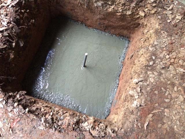
I shoveled the concrete into the hole and then used the shovel to level it out and tamp it down. Insert the rebar at this point, then use a trowel to smooth the top of the concrete and work out the air bubbles, tapping the top of the footing. Keep tapping, then tap some more. You want the air bubbles to work out.
The concrete needs to cure for at least three days before starting the piers. I managed to pour two 18" footings in a day and one 24" footing in a day for a total of three days. Then I started adding piers after three days.
I used 12" diameter cardboard forms. The forms will stick up roughly 8" past grade, 24" total height from the footing.


 I wanted the tops of all piers at the same elevation.
I used concrete pavers with a piece of plywood across the holes I already had to get an idea on how long to cut the form tubes. I measured from the top of the footing to the top of the paver. I used plywood to raise it if needed to achieve level.
An 8' 2x4 and string with a level were the tools used. I put the pavers where the first form would go, 8" above the ground, then used that as a base point to determine level for the other piers.
Once the forms were cut with an oscillating dremel tool, I cleared the top of the footing of debris/dirt and placed the forms. Then I shoved a bit of dirt in place and tamped it down so the forms wouldn't move around.
I leveled each tube, then leveled the tubes to each other. I started at one corner and worked my way around.
With the dirt packed into place, it provides some resistance to adjust the height of the tubes to obtain level. It also stops concrete from flowing out the bottom of the tube.
I had to trim a little bit off the bottom of the tubes due to the footing being uneven. I used an oscillating dremel tool, cutting the form in place.
Leveling can take a while as getting each form level, then leveling it to the other piers, then making sure the pier itself is still level is a process. Again, an inch off at this step compounds in each following step.
Once level was achieved all around, I added more dirt to each hole and packed it in so the tube wouldn't shift while shoveling concrete.


 I
used 2.5 bags of concrete per pier and about 2.5 gallons of water. I
used 5/16" J hooks embedded into the concrete. The future column bracket
will attach to the J hook. I tried to center the hooks in the pier,
with just a half inch sticking above the concrete. I will have to create
a recess in the bottom of the column for the bolt head. While they make
brackets that provide lift to avoid the recess all the other brackets
cost at least double.
I
used 2.5 bags of concrete per pier and about 2.5 gallons of water. I
used 5/16" J hooks embedded into the concrete. The future column bracket
will attach to the J hook. I tried to center the hooks in the pier,
with just a half inch sticking above the concrete. I will have to create
a recess in the bottom of the column for the bolt head. While they make
brackets that provide lift to avoid the recess all the other brackets
cost at least double.
The J hooks really don't do all that much, as I ended up nailing the brackets to the pier. You must nail the brackets to the concrete.The J hooks do help prevent drill walk.
Some brackets embed in the concrete themselves, but I wasn't sure how exact I'd be able to get that with embedding it in concrete. Looking back, it probably would have been fine as concrete takes a while to cure and that would give me time to measure and locate the bracket. These brackets are more expensive though.
I troweled the top of the pier smooth, even with the form.Tap the form to get air bubbles out. The more air bubbles, the less strength. Keep tapping!
Not all of my piers are exactly centered on the footing, some are off as much as 3 or 4". Maybe there's a a better way to dig footings than marking and then digging. A 2x4 frame could help as once I started digging the markings were gone.
The concrete tubes need to be stripped from the piers after a day or two. Just cut it down the side and pull it off. I only went a few inches below grade.
The concrete needs to dry a week for the concrete to be cured enough to bolt to the J bolts. I eventually added nails to the column brackets as a single J hook wasn't rigid enough. The J hooks do help keep the brackets in place as you drill a 1/8" hole for the masonry nails, acting as a guide.
I used a 1/8" masonry bit. Clear debris frequently and keep the water flowing to cool the bit, even then you will break bits.
You can drill for the nails 3 days after you pour the concrete, but let the pier cure a week before installation.


 Removing the Existing Deck
For many projects this will be the first step. I left my existing deck in place as long as possible, but it's time was up.
To remove the existing deck. I started with the railings which were surface mounted. They were very easy to remove by just pushing and pulling. They've been wobbly since day one. The screws were all rusted which means they weren't galvanized.

 I then removed the landing, the stair treads and stair stringers. I
bent all the nails over and hammered them flat to avoid any punctures.
I'm not sure any of the wood is worth keeping though I may try to
salvage the top and bottom rails of the railing. It's a steel U shape
and could make a good shelf bracket or similar.
I then removed the landing, the stair treads and stair stringers. I
bent all the nails over and hammered them flat to avoid any punctures.
I'm not sure any of the wood is worth keeping though I may try to
salvage the top and bottom rails of the railing. It's a steel U shape
and could make a good shelf bracket or similar.
I then removed each deck board.
 This
deck has columns on one side and is bolted to the house on the other. I
thought about adding temporary supports at the house side before
unbolting from the house, but instead I separated the joists and beams
from the ledger board at the house, then took down the columns.
This
deck has columns on one side and is bolted to the house on the other. I
thought about adding temporary supports at the house side before
unbolting from the house, but instead I separated the joists and beams
from the ledger board at the house, then took down the columns.
Wood Framing
The next step is starting the wood structure. I bought the lumber from a local yard. It's dryer wood than a big box store which means it's less likely to warp or bow. The yard also reviews each board and discards ones that are already warped. At a big box store the wood is wet and everything is bowed. The downside is that the yard is only open during the day when I'm at work, so I had to take time off.
I did have to use a trailer for the lumber as many of the boards were 16' long.
 The only thing the yard didn't have were 2x12x10'. That doesn't seem
to be a common size, though a 16' length is common. It was only $6 more
to get a little extra.
The only thing the yard didn't have were 2x12x10'. That doesn't seem
to be a common size, though a 16' length is common. It was only $6 more
to get a little extra.
I remeasured the center of all of the columns. A couple of the J hooks were off a bit, only half inch at most. That was pretty good I thought for the inexact nature of concrete.
I used a rasp to file out the bolt hole in the base bracket. While I'd prefer the brackets to be centered on the pier, I want the columns plumb and in line more.
Since the J hook and nut stick up past the bracket, I drilled the end of the columns using a 5/8" forstner bit and a 3/8" drill bit to clear the nut and bolt.


I then stained the bottom of the columns. I will stain all the structure as it provides a protective coat. The climbing wall I built a year ago was out of pressure treated wood and mildew/dirt started accumulating after two weeks. I sanded it down and stained it and it looks great a year later.
Plus any time you cut or drill into treated lumber, you need to retreat the cut end.
The columns won't stand up on their own, to get them place I clamped 2x4s as braces in 2 directions, to ensure it's plumb and straight before nailing in the base.
 With only a single bolt in the bottom of the bracket, I didn't like how much it wobbled. These brackets SHOULD be nailed.
I drilled (4) 1/8" holes through the holes in the base plate into the concrete for #9 2" masonry nails using a 1/8" masonry bit for pilot holes. I installed (4) nails into each bracket
When drilling concrete, use a masonry bit. A regular bit won't work. You need to remove the bit frequently from the hole to clear debris and keep the hole/bit wet to reduce heat.
Even doing this I broke three of the big box bits.
With the bases nailed, the columns were a lot more sturdy. The J hook probably isn't necessary at this point with the nails. What the J-hook did do is secure the bracket so my drilled holes didn't have any walk. That is helpful as I learned with my landing later.
The base bracket requires (6) 16d nails, 3 per side. Make sure they're galvanized. I set up the first beam, determined the cut line, took it down, cut it, then put it back up. This first beam will dictate the height of the other beams. I determined the height based on where I want the height of the finished deck, then subtracted deck board height and joist height. Measure the actual deck boards and joists, don't just assume as a 2x10 is actually 1.5x9.25.
I want to make sure the deck is level. After the fist column is up, I'll use a string and string level to mark the lines on the other columns before cutting them. At this point the other columns are just temporarily in place.
Once the top is cut, I'll notch the posts for the beam. Since one of my beams is (3) 2x's, those columns won't have a notch, the column will be cut shorter than the others for a bracket.
Make sure your notch is the width of the beam so the face of the beam is flush. This will help later when bracing the beam to the column. It also ensures the beam is fully bearing on the column. With a beam on the face of a column with through bolts, you're relying on the bolts, not the column to support the deck. The deck code does not allow that.
I used a circular saw to cut the beam, but the saw can't cut the entire thickness of the beam, so I cut around all 4 sides and then hand sawed the small connecting piece.
For the notches, I sawed what I could with a circular saw, then hand cut the rest of the notch. Since I cut all of my lines with a circular saw the end result looks clean.
For the shorter column, the bracket requires (6) 10d nails. Before attaching the bracket I cut a strip of flashing for the top of the column. This prevents water getting trapped between the beam and the column and prevents rot/deterioration.

 Beams
Beams
My beams are (2) 2x10s or (3) 2x10s. The beams required staggered 10d nails at 16" on center with (2) threaded nails at each end. For the (3) 2x10 beams, that pattern occurs on both sides, nailing to the center board.
The beams should be attached with 10d nails at 16" o.c. staggered. One top, next one 16" over at the bottom, repeating. Each end requires (2) threaded nails (or screws).
I've read it's best to install the through bolts at a diagonal instead of one over the other to prevent splitting, but I forgot to do that. The code shows them in line. You'll need a 5/8" washer for the carriage bolt head as the square head won't fit a 1/2" washer.
You'll need an 8" bolt to go through the post/beam. A 3/4" wrench will tighten the nuts. The through bolts shouldn't be spaced farther than 5" apart vertically. Mine are 2.5" from the top and 1.5" from the bottom.


 I used a 1/2" wood bit which will be a lot quicker than a regular
drill bit. Before I drilled all the way through, when just the tip of
the bit was through the back of the column, I drilled from the other
direction for a cleaner hole that reduces any tear out.
I used a 1/2" wood bit which will be a lot quicker than a regular
drill bit. Before I drilled all the way through, when just the tip of
the bit was through the back of the column, I drilled from the other
direction for a cleaner hole that reduces any tear out.
For the shorter beam, the bracket to the beam requires (12) 10d nails for each bracket.
The beams need to be braced in parallel back to the column, 1/2" lag screw and washer for diagonal 2x4 beam bracing.
Top of beams have flashing applied. This prevents water from being trapped between the beams at the joints which would cause rot.
When notching the columns for the end of the walk, I notched for a 10" beam, when my plans called for an 8" beam. The easiest fix is just buying a 2x10. I didn't want to have to buy new posts and I like the consistent beam depth anyway.
Once the beams were installed, the end beam/columns need to be braced in parallel. If you had (3) columns supporting a single beam, the deck code states to not brace the middle column. I do not have that condition.

 For bracing, use a 2x4 with 3" long 1/2" lag bolts and washers. One
bolt at each end centered on the beam/column.The bracing needs to be at a
45* angle to the columns/beams. I used a 3/8" drill bit as a pilot
hole.
For bracing, use a 2x4 with 3" long 1/2" lag bolts and washers. One
bolt at each end centered on the beam/column.The bracing needs to be at a
45* angle to the columns/beams. I used a 3/8" drill bit as a pilot
hole.
Joists
I'm using joist brackets (hurricane brackets) with the joists resting on the beams. Using this method, blocking needs to be between the joists along each beam. Otherwise the joists would twist.
I will add bridging mid span of the walkway since it's so long, to prevent it from feeling bouncy.
I didn't use joist brackets as it would add cost to the project. Joist brackets keep the top of the joist even with the top of the beam. The height reduction isn't an issue for my application.
When cutting the joists, I cut one end to square it off, as the rough lumber isn't always square. I was able to use some of the off cuts for the joist bridging. For the joists, I looked for the best looking joist that had the fewest knots for the rim joist. When cutting the joists to size, I'd try to position my cut to remove the end of the board with most knots, just to keep the joist looking it's best.
The brackets need (10) 4d nails. That's 1.5" long so they don't poke through the joists. I clamped the joists down when nailing and used a framing square/level.


When I eventually place the deck boards, I will notch or shim the deck boards (not the joists) as needed so deck boards will sit level. Not all joists are the same exact depth.
I used the 10d 3" threaded nails for the bridging. I offset and alternated each 2x10 so that I could nail directly into the bridging 2x10. Each one requires 4 nails, (2) each side.
I had a few bridges that were very short due to joists coming in to the center beam. I nailed a 3" nail all the way through or toe nailed it.
I added intermediate bridging mid span of the 12' walkway to reduce flex/bounce. The 8' patio didn't have any bounce.
At this point I stained the structure. It will be easier to stain now before I install the deck boards.
Where the two joists butt, I centered bridging on the joint and used (2) angle brackets on each side to attach bridging and joist.
The rim joists require (3) 10d nails into each perpendicular joist.
For the rim joist against the house I used (2) concealed joist brackets and (5) regular joist hanger. I clamped the rim joist into place, with a 3/4" plywood spacer against the house.
I had to mark for the concealed joist brackets, install them, then install the regular joist brackets in place.
(7) 6x6x8 PT columns
(6) 2x6x10' PT beam & joist
(1) 2x8x10' PT beam
(10) 2x10x8' PT beam
(1) 2x10x10 rim joist
(7) 2x10x12' PT joist & beam
(5) 2x10x16' PT joist
(15) 2x4x8 bracing & blocking
(8) 4x4x8 guard rail posts
(6) 2x12x8 stair stringers - bought (3) 2x12x16 - 8' length isn't a common size.
(5) 2x12x10 stair stringers - bought (3) 2x12x16 - 10' length isn't a common size.
Framing Subtotal: $910
Hardware:
(24) Joist Hold Down
(20) Lag Screw 1/2"x3"
(20) Guard Rail Joist Angle
(2) Double Post Cap base
(24) Joist Hurricane Ties
(4) Deck Tension Tie
(2) 1/2" threaded rod 72"
(2) Double Post Cap base
(24) Joist Hurricane Ties
(4) Deck Tension Tie
(2) 1/2" threaded rod 72"
(612) Nails 9 ga. 1.5" [(3) 1 lb box]
(36) Nails 16d 3.5" galvanized [(1) 1 lb box]
(104) Nails 10d 3" threaded [(1) 5 lb boxes]
(1) Butyl Flashing tape, 6" wide
(10) Angle Brackets
(36) Nails 16d 3.5" galvanized [(1) 1 lb box]
(104) Nails 10d 3" threaded [(1) 5 lb boxes]
(1) Butyl Flashing tape, 6" wide
(10) Angle Brackets
Hardware Subtotal: $650
Decking:
150 SF 6" wide 5/4 Decking (Composite would be 1.9x Cost, Cedar 1.77x Cost)
(3) 5 lb Pack 2 1/2" Deck screws (not nails)
(1) 1 lb Pack 3" Deck screws
48' of Railing panel
(3) Gallons of Stain/Sealer
Deck Subtotal: $680
Grand Total: $2,440
Decking:
150 SF 6" wide 5/4 Decking (Composite would be 1.9x Cost, Cedar 1.77x Cost)
(3) 5 lb Pack 2 1/2" Deck screws (not nails)
(1) 1 lb Pack 3" Deck screws
48' of Railing panel
(3) Gallons of Stain/Sealer
Deck Subtotal: $680
Grand Total: $2,440
Preliminary: tape measure, pencil/paper, Sketchup
Footings: tape measure, pencil, 2x4s, framing angle, nails, spray paint, flat nose shovel, mattock, post hole diggers, angle grinder, vice, wheel barrow, bucket, rubber mallet, level, string, string level, oscillating dremel tool, corded drill, (4) 1/8" masonry bit [keep your receipts, they will break]
Framing: tape measure, pencil, truck & trailer, circular saw, hand saw, corded drill, 3/8" drill bit, 5/8" forstner bit, rasp, hammer, string, string level, level
Deck and Railing: tape measure, pencil, cordless drill, circular saw, jig saw, framing angle, level, die grinder/cut off wheel, welder (optional)
Preliminary
I designed the deck in Sketchup first. This allowed me to see each connection and make sure everything fit right. First I measured the back of my house. It's crucial to start with good measurements of where the deck needs to go.
With determining joist spacing and overhang, it allowed me to figure out how to maximize the design. While a 2x12 would give me the overhang I needed, it also cost more.
The Sketchup model also gave me a reference so I could double check spacing, size, etc. I did reference the model often during construction.


It's likely your local planning department would issue a permit.
My locality has a deck guideline that is much less stringent that what I used, the prescriptive deck code. What you use is up to you, but you do need to at least conform to local codes.
While the code states you shouldn't frame joists to a beam from both sides. Allowing joists to span from opposite sides of the beam without appropriate consideration could potentially lead to a condition where beam capacity is exceeded. I factored capacity into my center beam design. Also, joists will be offset from each other, not back to back, which by that method alone may alleviate the code restriction. You wouldn't want to nail brackets back to back.
There are a lot of different types of hangers. Make sure you get ones that are appropriate for your application and joist/beam/stringer size.
I exchanged hardware items more than a couple times. I initially thought this would be my stringer hanger. It's not. Double check everything, and double check how hardware is installed before installing.
When cutting boards, especially ones that are 16' long, the board needs to be fully supported so the board doesn't fall, hit you, or bind the cutting blade.
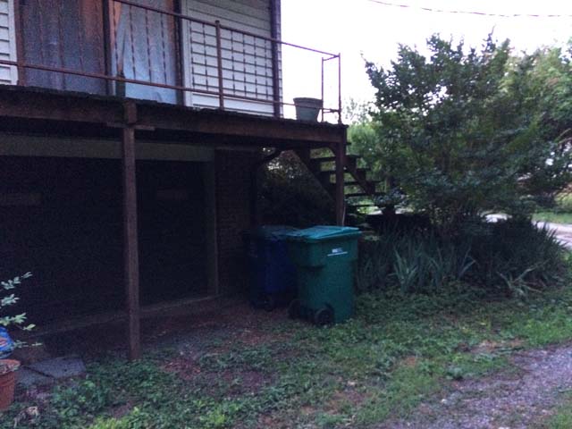 |
| The original deck. |
 |
| Beams should bolt directly to a column |
 |
| The column should attach to the footing and the footing should be below the frost line. |

 |
| Surface mounted rails are not sufficient. |

Armed with the dimensions from the Sketchup model, I laid out columns and footings. I used a 2x4 across the brick of the house for a straight edge and a 2x4 and framing angle perpendicular to the house for the column line. I used large nails stuck into the ground to stake two corners of the column, then measured the next column off the first.
Then I used 2x4s and the 3-4-5 method to ensure the first two columns were 90* angles off the house.
From the corner you measure 3' off one leg, 4' off the other leg, and the resulting leg of the triangle should be 5' if so you've got a square corner. If not, correct.
I used a stencil cut to 5.5"x5.5" and spray paint to mark the column. While that location will disappear once I dig the column, I want to be exact as possible. While footings can be off a few inches, being off one inch in the first step can translate to two inches in the second step and it compounds.
I measured the next two columns off the first two. Then I did the 3-4-5 off the first two. The patio part was in place and square. I cut stencils for the footings, 18" square and 24" square. I painted an outline with the stencil after centering it on the column outline.
The last two footings were done the same way.
I used rigid insulation to protect the spray paint from rain.
The paint outline gives me a clear delineation of where to dig. I need to dig down 24" so the footing sits below the frost line.
It's been raining off and on during this process. The rain will soften the ground and make digging a bit easier. From research the frost line where I'm located is between 6 and 12". The footing needs to be 12" lower than that. So making the bottom of the footing 24" below the ground is a safe bet, if not going too far and I prefer to overbuild.


I forgot how long it takes to dig holes. I figured a few days. It was a week.


 |
| The rebar connects the footing and the pier. |
I poured the water into the wheelbarrow first, then mixed the concrete in. I fully mixed each bag one at a time. After you mix a couple batches you'll get a good idea for the consistency, but it should be slightly moist.
I shoveled the concrete into the hole and then used the shovel to level it out and tamp it down. Insert the rebar at this point, then use a trowel to smooth the top of the concrete and work out the air bubbles, tapping the top of the footing. Keep tapping, then tap some more. You want the air bubbles to work out.
The concrete needs to cure for at least three days before starting the piers. I managed to pour two 18" footings in a day and one 24" footing in a day for a total of three days. Then I started adding piers after three days.
I used 12" diameter cardboard forms. The forms will stick up roughly 8" past grade, 24" total height from the footing.


I used concrete pavers with a piece of plywood across the holes I already had to get an idea on how long to cut the form tubes. I measured from the top of the footing to the top of the paver. I used plywood to raise it if needed to achieve level.
An 8' 2x4 and string with a level were the tools used. I put the pavers where the first form would go, 8" above the ground, then used that as a base point to determine level for the other piers.
Once the forms were cut with an oscillating dremel tool, I cleared the top of the footing of debris/dirt and placed the forms. Then I shoved a bit of dirt in place and tamped it down so the forms wouldn't move around.
I leveled each tube, then leveled the tubes to each other. I started at one corner and worked my way around.
With the dirt packed into place, it provides some resistance to adjust the height of the tubes to obtain level. It also stops concrete from flowing out the bottom of the tube.
I had to trim a little bit off the bottom of the tubes due to the footing being uneven. I used an oscillating dremel tool, cutting the form in place.
Leveling can take a while as getting each form level, then leveling it to the other piers, then making sure the pier itself is still level is a process. Again, an inch off at this step compounds in each following step.
Once level was achieved all around, I added more dirt to each hole and packed it in so the tube wouldn't shift while shoveling concrete.


The J hooks really don't do all that much, as I ended up nailing the brackets to the pier. You must nail the brackets to the concrete.The J hooks do help prevent drill walk.
Some brackets embed in the concrete themselves, but I wasn't sure how exact I'd be able to get that with embedding it in concrete. Looking back, it probably would have been fine as concrete takes a while to cure and that would give me time to measure and locate the bracket. These brackets are more expensive though.
I troweled the top of the pier smooth, even with the form.Tap the form to get air bubbles out. The more air bubbles, the less strength. Keep tapping!
Not all of my piers are exactly centered on the footing, some are off as much as 3 or 4". Maybe there's a a better way to dig footings than marking and then digging. A 2x4 frame could help as once I started digging the markings were gone.
The concrete tubes need to be stripped from the piers after a day or two. Just cut it down the side and pull it off. I only went a few inches below grade.
The concrete needs to dry a week for the concrete to be cured enough to bolt to the J bolts. I eventually added nails to the column brackets as a single J hook wasn't rigid enough. The J hooks do help keep the brackets in place as you drill a 1/8" hole for the masonry nails, acting as a guide.
I used a 1/8" masonry bit. Clear debris frequently and keep the water flowing to cool the bit, even then you will break bits.
You can drill for the nails 3 days after you pour the concrete, but let the pier cure a week before installation.


For many projects this will be the first step. I left my existing deck in place as long as possible, but it's time was up.
To remove the existing deck. I started with the railings which were surface mounted. They were very easy to remove by just pushing and pulling. They've been wobbly since day one. The screws were all rusted which means they weren't galvanized.


I then removed each deck board.

Wood Framing
The next step is starting the wood structure. I bought the lumber from a local yard. It's dryer wood than a big box store which means it's less likely to warp or bow. The yard also reviews each board and discards ones that are already warped. At a big box store the wood is wet and everything is bowed. The downside is that the yard is only open during the day when I'm at work, so I had to take time off.
I did have to use a trailer for the lumber as many of the boards were 16' long.

I remeasured the center of all of the columns. A couple of the J hooks were off a bit, only half inch at most. That was pretty good I thought for the inexact nature of concrete.
I used a rasp to file out the bolt hole in the base bracket. While I'd prefer the brackets to be centered on the pier, I want the columns plumb and in line more.
Since the J hook and nut stick up past the bracket, I drilled the end of the columns using a 5/8" forstner bit and a 3/8" drill bit to clear the nut and bolt.


I then stained the bottom of the columns. I will stain all the structure as it provides a protective coat. The climbing wall I built a year ago was out of pressure treated wood and mildew/dirt started accumulating after two weeks. I sanded it down and stained it and it looks great a year later.
Plus any time you cut or drill into treated lumber, you need to retreat the cut end.
The columns won't stand up on their own, to get them place I clamped 2x4s as braces in 2 directions, to ensure it's plumb and straight before nailing in the base.

I drilled (4) 1/8" holes through the holes in the base plate into the concrete for #9 2" masonry nails using a 1/8" masonry bit for pilot holes. I installed (4) nails into each bracket
When drilling concrete, use a masonry bit. A regular bit won't work. You need to remove the bit frequently from the hole to clear debris and keep the hole/bit wet to reduce heat.
Even doing this I broke three of the big box bits.
With the bases nailed, the columns were a lot more sturdy. The J hook probably isn't necessary at this point with the nails. What the J-hook did do is secure the bracket so my drilled holes didn't have any walk. That is helpful as I learned with my landing later.
The base bracket requires (6) 16d nails, 3 per side. Make sure they're galvanized. I set up the first beam, determined the cut line, took it down, cut it, then put it back up. This first beam will dictate the height of the other beams. I determined the height based on where I want the height of the finished deck, then subtracted deck board height and joist height. Measure the actual deck boards and joists, don't just assume as a 2x10 is actually 1.5x9.25.
I want to make sure the deck is level. After the fist column is up, I'll use a string and string level to mark the lines on the other columns before cutting them. At this point the other columns are just temporarily in place.
Once the top is cut, I'll notch the posts for the beam. Since one of my beams is (3) 2x's, those columns won't have a notch, the column will be cut shorter than the others for a bracket.
Make sure your notch is the width of the beam so the face of the beam is flush. This will help later when bracing the beam to the column. It also ensures the beam is fully bearing on the column. With a beam on the face of a column with through bolts, you're relying on the bolts, not the column to support the deck. The deck code does not allow that.
I used a circular saw to cut the beam, but the saw can't cut the entire thickness of the beam, so I cut around all 4 sides and then hand sawed the small connecting piece.
For the notches, I sawed what I could with a circular saw, then hand cut the rest of the notch. Since I cut all of my lines with a circular saw the end result looks clean.
For the shorter column, the bracket requires (6) 10d nails. Before attaching the bracket I cut a strip of flashing for the top of the column. This prevents water getting trapped between the beam and the column and prevents rot/deterioration.


My beams are (2) 2x10s or (3) 2x10s. The beams required staggered 10d nails at 16" on center with (2) threaded nails at each end. For the (3) 2x10 beams, that pattern occurs on both sides, nailing to the center board.
The beams should be attached with 10d nails at 16" o.c. staggered. One top, next one 16" over at the bottom, repeating. Each end requires (2) threaded nails (or screws).
I've read it's best to install the through bolts at a diagonal instead of one over the other to prevent splitting, but I forgot to do that. The code shows them in line. You'll need a 5/8" washer for the carriage bolt head as the square head won't fit a 1/2" washer.
You'll need an 8" bolt to go through the post/beam. A 3/4" wrench will tighten the nuts. The through bolts shouldn't be spaced farther than 5" apart vertically. Mine are 2.5" from the top and 1.5" from the bottom.

 |
| Flashing helps prevent water from getting trapped in the grooves between the boards. |


For the shorter beam, the bracket to the beam requires (12) 10d nails for each bracket.
The beams need to be braced in parallel back to the column, 1/2" lag screw and washer for diagonal 2x4 beam bracing.
Top of beams have flashing applied. This prevents water from being trapped between the beams at the joints which would cause rot.
When notching the columns for the end of the walk, I notched for a 10" beam, when my plans called for an 8" beam. The easiest fix is just buying a 2x10. I didn't want to have to buy new posts and I like the consistent beam depth anyway.
Once the beams were installed, the end beam/columns need to be braced in parallel. If you had (3) columns supporting a single beam, the deck code states to not brace the middle column. I do not have that condition.


Joists
I'm using joist brackets (hurricane brackets) with the joists resting on the beams. Using this method, blocking needs to be between the joists along each beam. Otherwise the joists would twist.
I will add bridging mid span of the walkway since it's so long, to prevent it from feeling bouncy.
I didn't use joist brackets as it would add cost to the project. Joist brackets keep the top of the joist even with the top of the beam. The height reduction isn't an issue for my application.
When cutting the joists, I cut one end to square it off, as the rough lumber isn't always square. I was able to use some of the off cuts for the joist bridging. For the joists, I looked for the best looking joist that had the fewest knots for the rim joist. When cutting the joists to size, I'd try to position my cut to remove the end of the board with most knots, just to keep the joist looking it's best.
The brackets need (10) 4d nails. That's 1.5" long so they don't poke through the joists. I clamped the joists down when nailing and used a framing square/level.


When I eventually place the deck boards, I will notch or shim the deck boards (not the joists) as needed so deck boards will sit level. Not all joists are the same exact depth.
I used the 10d 3" threaded nails for the bridging. I offset and alternated each 2x10 so that I could nail directly into the bridging 2x10. Each one requires 4 nails, (2) each side.
I had a few bridges that were very short due to joists coming in to the center beam. I nailed a 3" nail all the way through or toe nailed it.
I added intermediate bridging mid span of the 12' walkway to reduce flex/bounce. The 8' patio didn't have any bounce.
At this point I stained the structure. It will be easier to stain now before I install the deck boards.
Where the two joists butt, I centered bridging on the joint and used (2) angle brackets on each side to attach bridging and joist.
The rim joists require (3) 10d nails into each perpendicular joist.
For the rim joist against the house I used (2) concealed joist brackets and (5) regular joist hanger. I clamped the rim joist into place, with a 3/4" plywood spacer against the house.
I had to mark for the concealed joist brackets, install them, then install the regular joist brackets in place.
I used 1.5"
nails with 10d nails at the regular joist hangers that are toe nailed.
For the bridging to the joist next to the house, I used (2) angle brackets on each bridge since I could nail directly from the back side.
Guard Rail
The guard rail posts are installed next. They require (2) through bolts through the rim joist and then 2x4 blocking and brackets back to a main joist. Posts need to be strong, especially when you're eleven feet up. If your deck is higher than 30" from grade, the code requires a guard rail.
 The posts require 1/2" carriage bolts/washers/nuts and a tension bracket at the post and at the blocking back to the next joist.
If your post is at a corner/rim joist you wouldn't need the extra blocking/bracket at the next joist.
A 2x4 nailed back to a joist isn't enough as the nails could pull out, so a tension tie with a carriage bolt is at the post and back to the main joist using 2x4 bracing.
 The tension ties require 6 nails each. They can't be longer than 1.5" otherwise they would protrude through the brace. I used 3" threaded nails to attached the blocking through the joists.
A 1/2" wood drill bit is needed for the bracket/bolt.
I also placed all of my post blocking 1.5" below the top of the joists as I will add more 2x4 framing for the picture framed deck board edge.
My one corner post is in a tough to reach spot. Neither of my drills with bits fit. I had to borrow a right angle attachment.
I drilled the holes in the guard rail post first.
I ran a clamp from joist to joist for the guard rail post to rest. Then I would adjust the placement and clamp it to mark where to drill holes in the joist.


The top of the guard rail is 2x6's attached to the top of each post. A 2x4 at the top and 4" off the deck are attached to the inside face of the guard rail posts to attach the baluster. I'll discuss the rail panels later in the post.
Tension Tie
While the beams are braced, my deck wasn't braced in the opposite direction. I used (2) 6' 1/2" threaded rods with a tension tie at each end. Also (4) washers and (4) nuts at each end. I did two tension ties, one on the second joist from the outside both ways.
The bar extends 12" into the new deck and 5' into the joists of the house. Since the house joists are perpendicular, I added block between each joist to prevent pull. Worst case scenario, the existing joists could buckle if the deck were pulled.
The rods would need to be angled down towards the deck so that water doesn't creep into your house.
With my scenario, I attached the ties to a sun room that had accessible joists. I did have to drill a 1/2" hole through the joists for the threaded rod.
Just hand tight, the sway in the deck was completely gone. I did tension it somewhat, as one corner of the deck was closer than 3/4" to the sun room.
I ended up adding another tension tie at the other end of the deck parallel to the deck beams. There was a slight bit of sway.I did have to drill into and through my fascia panel. The tie is angled down towards the deck so water will drain away from the house.
Landing
The lower landing is tricky to layout. It's basically free standing and I have to measure off the as of yet unfinished deck which is also 5'-6' higher.
I built a temporary landing out of 2x4's just so I knew the size and could space footing and column locations off of that. I clamped (4) 2x4s together.
I clamped vertical 2x4's to the top of the deck, marked 3'-11" down and marked it after plumbing the 2x4's and then clamped more 2x4's to the verticals and put the temporary landing in place.
It sounds like a lot of work, but I need measurements off the deck and I need them lower. I will keep the temporary landing framing clamped together so I can check, footing locations, footing holes once dug, column locations, etc. I continually checked to ensure it was square.
You want to use the longest 2x4s you have to strike a straight line from the deck to landing.
Part of the issue with the landing is that it's on a slope. I'd prefer to normalize the footing depths, but it's a lot of effort for just a preference. I'll go 2' deep on each footing from the surface. While my other footings extended 8" above the ground I only need these to extend two inches as there is no way to hit them. They need to extend past the grade to block water from the column/bracket. With the size of the landing I don't need footings, I can just use concrete piers.
Each pier took 2.5 bags of concrete. I let the piers cure (2) days before stripping the forms and (3) days before drilling the holes for the brackets. I installed the nails/brackets after a week.
I didn't use J hooks this time around, which would have been nice just to hold the brackets in place to prevent walk while drilling. Without the bracket clamped down, the drill walked a bit when drilling the holes.I had to use a rasp to enlarged a few of the nail holes.
I ran the piers ~2" higher than grade. The landing ended up being a bit higher than I had planned as the beams are 5.5" tall plus the height of the bracket.
The columns are 6x6. The two short ones are 9" tall to account for the beam notch and the bracket. The lower columns are 20" tall.
The columns must be notched for the beam.
The beams will be (2) 2x6's while the joists are also 2x6s. I'm using joist brackets as I want to minimize the height of the landing. Each joist on the end will use concealed joist brackets.
What I should have done to lay out the landing is cut my stair stringers first and based the landing off of them. My landing ended up being a bit larger than I intended (by a couple inches), slightly off axis, and rotated a fraction of a degree. Once the deck is done, you won't be able to tell, but my stringers had to be spaced a bit wider top to bottom since the landing was off.


 Stairs
If your deck needs stairs, code requires them to be at least 36" wide.
Stair stringers are crucial. A good baseline for a stair is a 6" rise (height) and 12" run (length)
My stairs will be 6 7/16" and 11.5" You'll have to adjust for your space. You don't want to be shorter than 5" and 10".
You must use at least a 2x12 for the stringer. The stringers should be no greater than 18" apart.
The height from the top of the landing framing to deck framing was 45.25".
The distance from rim joist to rim joist was 79.57". Per the code, stairs with cut stringers shouldn't span more than 72", but 8" isn't going to cause the deck to implode.
You don't need blocking between stringers, because they shouldn't span far enough to need it. If your stringers span longer than 6', the solution is to add an intermediate landing.
I designed for 11.5" treads which would make it the width of the deck boards and provide a .5" overhang.
The risers worked out to 6 7/16". I will have 3/16" of 'play', but that's a small enough dimension to absorb.
I sketched out my layout on the 2x12. Double checking dimensions and angles. The angel of the stair is 29.2. I rounded it out to 30.
I use a 4' level and clamps as a guide for the circular saw as I cut each tread and riser. The cut was finished with a jig saw.
Once the first stringer was done, I traced it onto (4) others. On the fifth stringer I had cutting down to a science.
My first tread is even with the deck, this allows me to use a sloped joist hanger. If your top tread was a step down you would need a lower joist rim. The only way to achieve that is to have the columns at the end of the deck and the lower rim joist attached to the column.
The bottom of the stringers are notched and will attach to the landing beam with 2x4 blocking between attached to the beam and the stringers nailed to the 2x4 blocking.
Stairs to grade would be attached to a post with a 12" concrete pier and post.
The stringers fit into place and can be used temporarily without any hardware. To attach the top of the stringer, use a stringer hanger.
For the bottom, I used a 2x4 between the stringers with the 2x4 attached to the landing beam and the stringers attached to the 2x4. The stringers are notched and rest on the landing beam.
Each stair and riser is picture framed, which added a lot of additional blocking. It sure looks nice though!


Picture Framing
I always make things more complicated. I like the look of picture framing though it's recommended not to do it with treated wood as the mitered corners will eventually become uneven. That's why I initially considered composite. I'm using treated wood, but I have a plan.
You need additional 2x4 running along the rim joist to attach the end of the boards. My 2x4 is 2" off the rim joist. To support that 2x4 you need 2x4 from rim joist to next joist at 16" o.c.
For the stairs, I added a vertical 2x6 at each riser to catch the picture framing. A 2x4 parallel with the tread rests on the 2x6 and on an additional 2x4 at the riser end of the tread.
The mitered corners of the picturing framing need to be doweled. If they are just nailed, contraction & expansion will ruin the joist. We'll see if doweling works. I ended up not doweling, and put some screws through the mitered ends.
With my stairs not square I installed the 12.5" tread deck framing first, then I cut the long section of tread to width. The miters wont' be 45* so I put it in place and traced the miter from the short framing onto the long framing.


For the bridging to the joist next to the house, I used (2) angle brackets on each bridge since I could nail directly from the back side.
Guard Rail
The guard rail posts are installed next. They require (2) through bolts through the rim joist and then 2x4 blocking and brackets back to a main joist. Posts need to be strong, especially when you're eleven feet up. If your deck is higher than 30" from grade, the code requires a guard rail.

If your post is at a corner/rim joist you wouldn't need the extra blocking/bracket at the next joist.
A 2x4 nailed back to a joist isn't enough as the nails could pull out, so a tension tie with a carriage bolt is at the post and back to the main joist using 2x4 bracing.

A 1/2" wood drill bit is needed for the bracket/bolt.
I also placed all of my post blocking 1.5" below the top of the joists as I will add more 2x4 framing for the picture framed deck board edge.
My one corner post is in a tough to reach spot. Neither of my drills with bits fit. I had to borrow a right angle attachment.
I drilled the holes in the guard rail post first.
I ran a clamp from joist to joist for the guard rail post to rest. Then I would adjust the placement and clamp it to mark where to drill holes in the joist.
 |
| I used a round over router bit for the top edges of the guard rail. It looks better and is smoother. |

 |
| Mitered corners provide a cleaner look. |


The top of the guard rail is 2x6's attached to the top of each post. A 2x4 at the top and 4" off the deck are attached to the inside face of the guard rail posts to attach the baluster. I'll discuss the rail panels later in the post.
Tension Tie
While the beams are braced, my deck wasn't braced in the opposite direction. I used (2) 6' 1/2" threaded rods with a tension tie at each end. Also (4) washers and (4) nuts at each end. I did two tension ties, one on the second joist from the outside both ways.
The bar extends 12" into the new deck and 5' into the joists of the house. Since the house joists are perpendicular, I added block between each joist to prevent pull. Worst case scenario, the existing joists could buckle if the deck were pulled.
The rods would need to be angled down towards the deck so that water doesn't creep into your house.
With my scenario, I attached the ties to a sun room that had accessible joists. I did have to drill a 1/2" hole through the joists for the threaded rod.
Just hand tight, the sway in the deck was completely gone. I did tension it somewhat, as one corner of the deck was closer than 3/4" to the sun room.
I ended up adding another tension tie at the other end of the deck parallel to the deck beams. There was a slight bit of sway.I did have to drill into and through my fascia panel. The tie is angled down towards the deck so water will drain away from the house.
Landing
The lower landing is tricky to layout. It's basically free standing and I have to measure off the as of yet unfinished deck which is also 5'-6' higher.
I built a temporary landing out of 2x4's just so I knew the size and could space footing and column locations off of that. I clamped (4) 2x4s together.
I clamped vertical 2x4's to the top of the deck, marked 3'-11" down and marked it after plumbing the 2x4's and then clamped more 2x4's to the verticals and put the temporary landing in place.
It sounds like a lot of work, but I need measurements off the deck and I need them lower. I will keep the temporary landing framing clamped together so I can check, footing locations, footing holes once dug, column locations, etc. I continually checked to ensure it was square.
You want to use the longest 2x4s you have to strike a straight line from the deck to landing.
Part of the issue with the landing is that it's on a slope. I'd prefer to normalize the footing depths, but it's a lot of effort for just a preference. I'll go 2' deep on each footing from the surface. While my other footings extended 8" above the ground I only need these to extend two inches as there is no way to hit them. They need to extend past the grade to block water from the column/bracket. With the size of the landing I don't need footings, I can just use concrete piers.
Each pier took 2.5 bags of concrete. I let the piers cure (2) days before stripping the forms and (3) days before drilling the holes for the brackets. I installed the nails/brackets after a week.
I didn't use J hooks this time around, which would have been nice just to hold the brackets in place to prevent walk while drilling. Without the bracket clamped down, the drill walked a bit when drilling the holes.I had to use a rasp to enlarged a few of the nail holes.
I ran the piers ~2" higher than grade. The landing ended up being a bit higher than I had planned as the beams are 5.5" tall plus the height of the bracket.
The columns are 6x6. The two short ones are 9" tall to account for the beam notch and the bracket. The lower columns are 20" tall.
The columns must be notched for the beam.
The beams will be (2) 2x6's while the joists are also 2x6s. I'm using joist brackets as I want to minimize the height of the landing. Each joist on the end will use concealed joist brackets.
What I should have done to lay out the landing is cut my stair stringers first and based the landing off of them. My landing ended up being a bit larger than I intended (by a couple inches), slightly off axis, and rotated a fraction of a degree. Once the deck is done, you won't be able to tell, but my stringers had to be spaced a bit wider top to bottom since the landing was off.


If your deck needs stairs, code requires them to be at least 36" wide.
Stair stringers are crucial. A good baseline for a stair is a 6" rise (height) and 12" run (length)
My stairs will be 6 7/16" and 11.5" You'll have to adjust for your space. You don't want to be shorter than 5" and 10".
You must use at least a 2x12 for the stringer. The stringers should be no greater than 18" apart.
The height from the top of the landing framing to deck framing was 45.25".
The distance from rim joist to rim joist was 79.57". Per the code, stairs with cut stringers shouldn't span more than 72", but 8" isn't going to cause the deck to implode.
You don't need blocking between stringers, because they shouldn't span far enough to need it. If your stringers span longer than 6', the solution is to add an intermediate landing.
I designed for 11.5" treads which would make it the width of the deck boards and provide a .5" overhang.
The risers worked out to 6 7/16". I will have 3/16" of 'play', but that's a small enough dimension to absorb.
I sketched out my layout on the 2x12. Double checking dimensions and angles. The angel of the stair is 29.2. I rounded it out to 30.
I use a 4' level and clamps as a guide for the circular saw as I cut each tread and riser. The cut was finished with a jig saw.
Once the first stringer was done, I traced it onto (4) others. On the fifth stringer I had cutting down to a science.
My first tread is even with the deck, this allows me to use a sloped joist hanger. If your top tread was a step down you would need a lower joist rim. The only way to achieve that is to have the columns at the end of the deck and the lower rim joist attached to the column.
The bottom of the stringers are notched and will attach to the landing beam with 2x4 blocking between attached to the beam and the stringers nailed to the 2x4 blocking.
Stairs to grade would be attached to a post with a 12" concrete pier and post.
The stringers fit into place and can be used temporarily without any hardware. To attach the top of the stringer, use a stringer hanger.
For the bottom, I used a 2x4 between the stringers with the 2x4 attached to the landing beam and the stringers attached to the 2x4. The stringers are notched and rest on the landing beam.
Each stair and riser is picture framed, which added a lot of additional blocking. It sure looks nice though!


Picture Framing
I always make things more complicated. I like the look of picture framing though it's recommended not to do it with treated wood as the mitered corners will eventually become uneven. That's why I initially considered composite. I'm using treated wood, but I have a plan.
You need additional 2x4 running along the rim joist to attach the end of the boards. My 2x4 is 2" off the rim joist. To support that 2x4 you need 2x4 from rim joist to next joist at 16" o.c.
For the stairs, I added a vertical 2x6 at each riser to catch the picture framing. A 2x4 parallel with the tread rests on the 2x6 and on an additional 2x4 at the riser end of the tread.
The mitered corners of the picturing framing need to be doweled. If they are just nailed, contraction & expansion will ruin the joist. We'll see if doweling works. I ended up not doweling, and put some screws through the mitered ends.
With my stairs not square I installed the 12.5" tread deck framing first, then I cut the long section of tread to width. The miters wont' be 45* so I put it in place and traced the miter from the short framing onto the long framing.


Landing Stairs
The landing is on a slope but I want stairs coming off all three sides. This is roughly one step on one side, two on the next, four on the one after.
I also want the stairs to fan out in a five sided shape. Like I said, I like to over complicate things.
I added (7) 12" tall 12" diameter piers to catch the stair stringers. I have (3) 4 tread stringers, (2) 3 tread stringers (1) 2 tread stringers and (3) 1 tread stringers. I also have diagonal stringers for my (5) sided shape, (2) 4 tread diagonals, (1) 2 tread diagonal, and (1) 1 tread diagonal.
The outside (4) tread stringers are attached to a vertical 4x4 and bracket. One 4x4 is cut at the top of the tread, the other serves as a guard rail post. The rest of the stringers are attached to a 2x4 with the stringers bearing on the 2x4. A 2x6 would have been too tall, though I may should have doubled the 2x4. An angle bracket attaches the 2x4 to the pier.


 My five sided stairs have a lot of angles. I started on one end and worked my way around. I would cut the first board a bit long, nail it in place and then skip the next section and attach the next board. I would then trace the miter onto the board in between.
Decking
I used 5/4's treated 6" wide deck board. Two screws at each joist spaced 1" off the edge of the deck board. While many people won't notice the nails if they are spaced uniformly, nails that are all over the place are much more noticeable.
The boards were spaced with a .25" gap. I used scrap piece of MDF between the boards.


 Handrail
A deck with four or more risers requires a hand rail on one side. The rail should run continuously from the lowest riser to the highest riser, returning to the post on each end with brackets at 4' on center.
I don't want a handrail, so I'm not going to install one. I will have a guard rail, so if I decided I want a hand rail I could add one later.
Rail Panels
Per code, the rail panels should be sized so that a 4"x4" ball won't fit through any single opening. I initially planned to use galvanized goat paneling, which has 4x4 openings. When it came time to actually purchase the panels, no one had them in stock. I used cattle fencing which has 6"x6" openings.
The landing is on a slope but I want stairs coming off all three sides. This is roughly one step on one side, two on the next, four on the one after.
I also want the stairs to fan out in a five sided shape. Like I said, I like to over complicate things.
I added (7) 12" tall 12" diameter piers to catch the stair stringers. I have (3) 4 tread stringers, (2) 3 tread stringers (1) 2 tread stringers and (3) 1 tread stringers. I also have diagonal stringers for my (5) sided shape, (2) 4 tread diagonals, (1) 2 tread diagonal, and (1) 1 tread diagonal.
The outside (4) tread stringers are attached to a vertical 4x4 and bracket. One 4x4 is cut at the top of the tread, the other serves as a guard rail post. The rest of the stringers are attached to a 2x4 with the stringers bearing on the 2x4. A 2x6 would have been too tall, though I may should have doubled the 2x4. An angle bracket attaches the 2x4 to the pier.


Decking
I used 5/4's treated 6" wide deck board. Two screws at each joist spaced 1" off the edge of the deck board. While many people won't notice the nails if they are spaced uniformly, nails that are all over the place are much more noticeable.
The boards were spaced with a .25" gap. I used scrap piece of MDF between the boards.


A deck with four or more risers requires a hand rail on one side. The rail should run continuously from the lowest riser to the highest riser, returning to the post on each end with brackets at 4' on center.
I don't want a handrail, so I'm not going to install one. I will have a guard rail, so if I decided I want a hand rail I could add one later.
Rail Panels
Per code, the rail panels should be sized so that a 4"x4" ball won't fit through any single opening. I initially planned to use galvanized goat paneling, which has 4x4 openings. When it came time to actually purchase the panels, no one had them in stock. I used cattle fencing which has 6"x6" openings.
I notched the to 2x4 with a 3/8" rabbet with a 1/2" total height. I did this to the bottom 2x4 as well, with the rabbet on the side against the guard rail post. The 2x4s are nailed to the face of the post.
The bottom 2x4 needs to be 4" off the deck. The top 2x4 is flush with the top of the post. A 2x6 will attach to the post and top 2x4.
I used a pneumatic cut off wheel to cut the panels to size. They are wedged into the rabbet which holds the panels still. the panels are sandwiched between the 2x4's and posts so they aren't going anywhere. If you do have any panels that aren't wedged tight, a staple from the back in the rabbet or a shim can solve that issue.


 The rail panels would typically slope with the stairs, but I wanted all of the lines straight. I ended up cutting and having the panels welded at the stairs to follow the stair slope. It was a fair amount of extra work, but it looks good. After welding I sprayed the panels with galvanized paint.


Conclusion
This took 3x longer than expected which is typical for my projects. Getting my concrete piers in the right spot proved tricky, and even worse when installing piers for stairs as measurements aren't straight but angled. I don't know what I could have done better, maybe creating a string line system for reference and putting semi-permanent stakes in the ground. Good concrete bits are hard to find. I went though a lot of them.
Picturing framing requires so much extra wood, but I like the look. Wanting the rail panels lines to be straight also added a fair amount of time and trouble.
I didn't want a (1) tread riser off my landing, but the column brackets dictated I add a riser. I may could have cantilevered the beam farther on that side, just a foot would have resolved the height issue. I didn't account for the height of the column bracket which is what threw it off.
I love the way the deck looks. Even though a few things are off, you can't tell it from looking. Once I was done I used a water sealer on all horizontal surfaces for added protection. I put a reminder in my phone to seal the deck again next year so I don't forget. I may be able to go two years between sealing. They way to check is to see if water pools or is absorbed by the wood.
I love the way the deck looks. Even though a few things are off, you can't tell it from looking. Once I was done I used a water sealer on all horizontal surfaces for added protection. I put a reminder in my phone to seal the deck again next year so I don't forget. I may be able to go two years between sealing. They way to check is to see if water pools or is absorbed by the wood.
One Year Later Update
A wood deck needs to be resealed yearly. One year later the deck boards were looking faded, but a few coats of sealer brought it right back to new.


A wood deck needs to be resealed yearly. One year later the deck boards were looking faded, but a few coats of sealer brought it right back to new.


While my miters were perfect a year ago, they've all separated to some degree. The reason to seal yearly is to maintain the waterproof properties.
No comments:
Post a Comment